Matrox Imaging Library (MIL) 10 Update 74
Matrox Radient eV-CL release notes
February 2019
(c) Copyright Matrox Electronic Systems Ltd., 1992-2019.
This document outlines what is new with the MIL 10 driver for the Matrox Radient eV-CL and explains the current limitations and particularities.
It also presents last-minute information that did not make it into the manual or on-line help. Note that this help file serves to complement your manual. The information found in this file overrides your formally documented material.
Contents
1. MIL 10 driver for Matrox Radient eV-CL
1.1 What’s new in MIL 10 Update 74
1.1.3 Known limitations and particularities
1.2 What’s new in MIL 10 Update 49
1.2.4 Known limitations and particularities
1.3 What’s new in MIL 10 Update 27
2. Supported operating systems
3. Location of examples (in the help file)
1.1 What’s new in MIL 10 Update 74
Note that MIL 10 Update 74 is a cumulative update, including all content from MIL Update 49 and 27.
1.1.1 Standards compliance
The MIL 10 driver for Matrox Radient eV-CL supports the following standards:
· Camera Link® version 2.0.
· GenICam™ GenApi version 3.1.0
· GenICam™ GenCP Camera Link Module version 1.2.
· GenICam™ for Camera Link® (CLProtocol) version 1.1. Note that this requires a third-party CLProtocol communication library (DLL) which is supplied by the camera vendor.
1.1.2 Summary of new features
· Added support for firmware updates on Version >= 300 of the dual-Base and single-Full boards, and Version >= 008 of the quad-Base and dual-Full boards (PCB Y7469-03).
1.1.3 Known limitations and particularities
· Installing this update removes Matrox Intellicam’s support for the Matrox CronosPlus, Matrox Vio and IEEE 1394 IIDC devices.
· Building the MIL examples using Visual Studio 2015 or 2017 also requires the presence of Windows SDK version 8.1, which is installed from the Visual Studio setup.
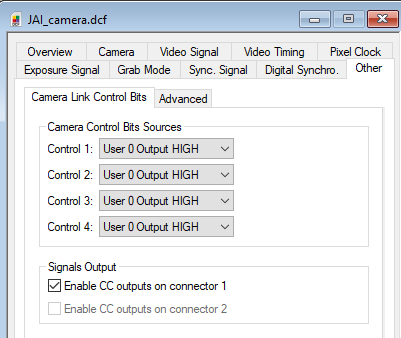
· When using JAI® cameras, the Camera Link Camera Control bits on the Matrox Radient eV-CL must be activated in order for the communication with the camera (either with JAI or Matrox software) to be stable. They can be activated using Intellicam in the ‘Other’ tab in the DCF dialog.
· Editing a DCF for Camera Link within Matrox Intellicam will close an open Feature Browser window. What’s more, re-opening a Feature Browser window may be subject to a noticeable delay due to camera initialization. To avoid this behavior, uncheck the ‘Automatically compute registers…’ checkbox from the ‘Preferences – Register Compute’ menu tab. However, a manual DCF compute from ‘DCF – Compute Registers’ will be required thereafter.
· Minimizing the Feature Browser window hides it from view but it can be re-opened for viewing by clicking on the Feature Browser icon.
· DCFs with manually edited register values for OPTO_AUX_IN0, OPTO_AUX_IN1, LVDS_AUX_IN2, LVDS_AUX_IN3, TTL_AUX_IO_4, TTL_AUX_IO_5, TTL_AUX_IO_6, OPTO_AUX_IN8, OPTO_AUX_IN9, LVDS_AUX_IN10, LVDS_AUX_IN11, TTL_AUX_IO_12, TTL_AUX_IO_13, TTL_AUX_IO_14 will need to have these values adjusted by adding 0x1000 (ex. 0x64 becomes 0x1064).
1.1.4 Software bug fixes
· MdigInquireFeature(): Fixed incomplete string issue when inquiring a feature as a MIL_STRING. Features such as DeviceTemperature can change between the inquire of its string size and of its string data. For example, when we inquire the size, the temperature is 50 degrees, and when we inquire the data, the temperature becomes 50.1. The string size changed between the 2 inquires (size and data), which results in missing characters.
· Fixed issue when setting a common grab or timer trigger using a custom DCF.
· Fixed possible application crash when performing a firmware update.
· Fixed issue when setting MdigControl(M_IO_MODE, M_OUTPUT) of an LVDS signal.
· Fixed issue when setting MdigControl(M_IO_SOURCE) to M_DISABLE (LVDS signals become tri-state).
· Fixed issue with a DCF using tap reversal on the 8th and 9th tap in Camera Link deca mode.
· Fixed issue where the default values of the Camera Link Camera Control bits were not properly reset when freeing the digitizer.
· Fixed issue when setting MdigControl(M_ROTARY_ENCODER_POSITION_TRIGGER_DOUBLE) with M_ROTARY_ENCODERn (where n is a number between 1 and 4).
· Fixed precision issue when using quadrature encoders with fractional values.
· Fixed possible crash when using data latch when internal buffer could not be allocated.
· MILConfig: Fixed issue with the “Max Temperature Recorded” value in the Radient eV-CL page (it was returning the current temperature).
1.1.5 Firmware bug fixes
· When using the second acquisition path of the Radient eV-CL dual-Full, the quadrature encoder inputs now use those from the AUX I/O B connector to be compatible with the Radient eCL.
1.1.6 Behavior changes
· When allocating a color grab buffer without specifying if it is packed or planar, it will now be planar.
1.2 What’s new in MIL 10 Update 49
Note that MIL 10 Update 49 is a cumulative update, including all content from MIL Update 27.
1.2.1 Standards compliance
The MIL 10 driver for Matrox Radient eV-CL supports the following standards:
· Camera Link® version 2.0.
· GenICam™ standard version 3.0.1.
· GenICam™ for Camera Link® (CLProtocol). Note that this requires a third-party CLProtocol communication library (DLL) which is supplied by the camera vendor.
· GenICam™ GenCP Camera Link Module version 1.0.
1.2.2 Summary of new features
The following features are new for this release:
· Added support for Teledyne DALSA Linea and Teledyne e2v Eliixa line-scan color cameras.
The missing red or blue value of a destination pixel is interpolated from the left and right values in the source; whereas the green value of a destination pixel is used as is from the source.
· Added support for hardware gain and offset correction per pixel; see M_SHADING_CORRECTION below.
· Added support to debounce any of the auxiliary input signals (the default is the same as Update 27 but can be configured using a DCF).
· Added a pulse signal multiplier on all auxiliary input signals (configured using a DCF).
· Added new control types to deal with triggers that happen while the grab and timers are active; see M_GRAB_TRIGGER_OVERLAP and M_TIMER_TRIGGER_OVERLAP below.
· Added new control types that allow the rotary decoder to start generating triggers only upon reaching a set counter value and then to generate a trigger at a set interval (change) in counter value; see M_ROTARY_ENCODER_* below.
· Added a timer trigger divider; see M_TIMER_TRIGGER_RATE_DIVIDER below.
1.2.3 API enhancements
· Additions to MdigControl()/MdigInquire():
|
Sets whether to perform a gain and offset correction per pixel. When grabbing to a buffer in Host memory, your digitizer performs the shading correction operation using following equation: (Grab Image x M_SHADING_CORRECTION_GAIN_ID) + M_SHADING_CORRECTION_OFFSET_ID Each row of gain and offset values is applied to the equivalent row of the grabbed image. To set the gain and provide an offset for shading correction, use M_SHADING_CORRECTION_OFFSET_ID and M_SHADING_CORRECTION_GAIN_ID, respectively. |
||
|
|
Enables shading correction. |
|
|
M_DISABLE |
Disables shading correction. |
|
|
M_SHADING_CORRECTION_GAIN_ID |
Sets the buffer containing the gain values that your digitizer should use when it performs a shading correction. To enable on-board shading correction and provide an offset, use M_SHADING_CORRECTION and M_SHADING_CORRECTION_OFFSET_ID, respectively. |
|
|
|
M_NULL |
Specifies to not apply a gain when performing a shading correction. |
|
ShadingCorrectionGainID |
Specifies the identifier of an M_IMAGE buffer containing the gain values. The buffer must be allocated as a single-band unsigned 8-bit or unsigned 16-bit buffer. It is interpreted as a fixed point buffer with 2-bits for the numerical part. Use M_SHADING_CORRECTION_GAIN_FIXED_POINT to set the number of bits for the fractional part. It can have an X-size of up to 16384 pixels and a Y-size equal to the size of the DCF. |
|
|
M_SHADING_CORRECTION_GAIN_FIXED_POINT |
Sets the number of bits for the fraction part of the fixed point gain value that your digitizer should use when it performs a shading correction. To enable on-board shading correction and provide an offset, use M_SHADING_CORRECTION, M_SHADING_CORRECTION_GAIN_ID, and M_SHADING_CORRECTION_OFFSET_ID, respectively. |
|
|
|
0<= Value <16 |
Specifies the fractional part of the fixed point gain value. |
|
M_SHADING_CORRECTION_OFFSET_ID |
Sets the buffer containing the offset values that your digitizer should use when it performs a shading correction. To enable on-board shading correction and provide a gain, use M_SHADING_CORRECTION and M_SHADING_CORRECTION_GAIN_ID, respectively. |
|
|
|
M_NULL |
Specifies to not apply an offset when performing a shading correction. |
ShadingCorrectionOffsetID
|
Specifies the identifier of an M_IMAGE buffer containing the offset values. The buffer must be allocated as a signed 8-bit or signed 16-bit buffer. |
|
|
Sets how to deal with a new trigger that occurs while a grab is in progress. |
||
|
|
M_DEFAULT |
Same as M_RESET or value specified in DCF. |
|
M_PREVIOUS_FRAME |
Specifies that a trigger received, while the grab is in progress, will be latched (stored). As soon as the current grab finishes, a new grab will be started. |
|
|
M_OFF |
Specifies that a new trigger is ignored. |
|
|
M_RESET |
Specifies that the current grab will be immediately stopped and a new grab will be started. |
|
|
M_ROTARY_ENCODER_POSITION_START_TRIGGER (+ M_ROTARY_ENCODERn) |
Sets the rotary decoder's counter value upon which to start generating triggers, when M_ROTARY_ENCODER_OUTPUT_MODE is set to M_POSITION_TRIGGER_MULTIPLE. If it is not set to this value, then M_ROTARY_ENCODER_POSITION_START_TRIGGER is ignored. |
|
|
|
Specifies the value of the counter upon which to start generating triggers. |
|
|
M_ROTARY_ENCODER_OUTPUT_MODE (+ M_ROTARY_ENCODERn) |
Sets the rotary decoder's counter value and/or the direction of movement upon which the rotary decoder should output a pulse. |
|
|
additional control values found in references |
M_POSITION_TRIGGER_MULTIPLE |
Specifies to start triggering only when the counter value set with M_ROTARY_ENCODER_POSITION_START_TRIGGER is reached and then to generate a trigger at a set interval (change) in counter value. Set the interval with M_ROTARY_ENCODER_POSITION_TRIGGER. |
|
M_ROTARY_ENCODER_POSITION_TRIGGER (+ M_ROTARY_ENCODERn) |
Sets the rotary decoder's counter value at which a trigger is generated. |
|
|
|
0 < Value <= 0xFFFFFFFF |
Specifies the counter value or change in counter
value at which to generate a trigger. If M_ROTARY_ENCODER_OUTPUT_MODE is set to M_POSITION_TRIGGER_MULTIPLE, this will specify the change in counter value at which to generate a trigger, beginning at the counter value specified by M_ROTARY_ENCODER_POSITION_START_TRIGGER. If M_ROTARY_ENCODER_OUTPUT_MODE is set to M_POSITION_TRIGGER, this will specify the counter value at which to generate a trigger each time this value is reached. If M_POSITION_TRIGGER is set to any other control value, this value will be ignored. |
|
M_TIMER_TRIGGER_OVERLAP + M_TIMERn |
Sets how to deal with a new trigger that occurs while the associated timer has not yet expired (both its delay and duration). |
|
|
|
M_DEFAULT |
Same as M_RESET or value specified in DCF. |
|
M_LATCH |
Specifies that a trigger received, while the associated timer has not expired, will be latched (stored). As soon as the current timer expires, a new trigger is issued. |
|
|
M_OFF |
Specifies that a new trigger is ignored. |
|
|
M_RESET |
Specifies that a new trigger automatically resets the timer (regardless of whether it is in its delay or active period) and then restarts the timer. This process will repeat for each new trigger received. |
|
|
Sets the frequency to accept trigger pulses (for example, if set to 2, the first trigger pulse is ignored and the second is accepted). |
||
|
|
M_DEFAULT |
Specifies the default value; the default value is 1. |
|
|
1 <= Value <= 255 |
Specifies the frequency with which to accept a trigger out of a series of trigger pulses. Note that, if set to 1, all trigger pulses are accepted. |
Example 1
In the following code snippet, an encoder is used to trigger a grab when a certain position is reached. 20 frames of 1000 lines each, or 20000 lines, are grabbed at which point the grab moves slightly to the right and repeats the process in reverse. The LinearEncoderScan animation, found on the RadienteVCLAnimation page in this section of the help file, illustrates this example.
/* The camera must be set to trigger the acquisition of a line on the rising edge of the timer output signal. */
/* Reset the decoder counter to 0. */
MdigControl(MilDigitizer, M_ROTARY_ENCODER_POSITION, 0);
/* Program the timer to trigger on a decoder signal. */
MdigControl(MilDigitizer, M_TIMER_CLOCK_SOURCE, M_SYSCLK);
MdigControl(MilDigitizer, M_TIMER_DELAY, timerDelayInUs);
MdigControl(MilDigitizer, M_TIMER_DURATION, timerDurationInUs);
MdigControl(MilDigitizer, M_TIMER_TRIGGER_SOURCE, M_ROTARY_ENCODER);
MdigControl(MilDigitizer, M_TIMER_STATE, M_ENABLE);
/* Program the decoder to start triggering when position 1000 is reached
then continue triggering at a multiple of '1'. */
MdigControl(MilDigitizer, M_ROTARY_ENCODER_OUTPUT_MODE, M_POSITION_TRIGGER_MULTIPLE);
MdigControl(MilDigitizer, M_ROTARY_ENCODER_POSITION_START_TRIGGER, 1000);
MdigControl(MilDigitizer, M_ROTARY_ENCODER_POSITION_TRIGGER, 1);
/* Start MdigProcess to grab a sequence (strip) of 20 frames of 1000 lines each for
a total of 20000 lines (bufferingSize == 20). */
MdigProcess(MilDigitizer, MilGrabBufferList, bufferingSize,
M_SEQUENCE, M_SYNCHRONOUS, ProcessingFunction, &UserHookData);
/* Once the end of sequence is reached, the stage will start scanning in the
other direction (the decoder counter will decrement). */
/* Program the decoder to start triggering when counter value 21000 is reached
then continue triggering at a multiple of '1'. */
MdigControl(MilDigitizer, M_ROTARY_ENCODER_POSITION_START_TRIGGER, 21000);
/* Start MdigProcess to grab a sequence of 20 frames of 1000 lines each for
a total of 20000 lines (bufferingSize == 20). */
MdigProcess(MilDigitizer, MilGrabBufferList, bufferingSize,
M_SEQUENCE, M_SYNCHRONOUS, ProcessingFunction, &UserHookData);
Example 2
In the following code snippet, the board’s decoder is set to trigger a pulse only when a linear stage is moving forward. The counter decrements when the stage moves in reverse. The grab is only triggered when the counter hits a new positive value; as such, no line that was already grabbed will be grabbed again. The RotaryLogScan animation, found on the RadienteVCLAnimation2 page in this section of the help file, illustrates this example.
/* The camera must be set to trigger the acquisition of a line on the rising edge of the timer output signal. */
/* Set the rotary decoder to send a trigger only when the stage is moving forward. */
MdigControl(MilDigitizer, M_ROTARY_ENCODER_DIRECTION, M_FORWARD);
/* Specifies to set the counter to 0xFFFFFFFF upon a decrement. */
MdigControl(MilDigitizer, M_ROTARY_ENCODER_FORCE_VALUE_SOURCE, M_STEP_BACKWARD_WHILE_POSITIVE);
/* Specifies to output a pulse upon a rotary decoder counter
increment, only if the counter value is in the range of 0x0 to
0x7FFFFFFF
before the increment occurs; when interpreting the
counter value as signed, this would be the positive counter value
range. */
MdigControl(MilDigitizer, M_ROTARY_ENCODER_OUTPUT_MODE, M_STEP_FORWARD_WHILE_POSITIVE);
/* Set the rotary decoder counter to 0. */
MdigControl(MilDigitizer, M_ROTARY_ENCODER_POSITION_TRIGGER, 0);
/* Set the signal that the timer should output at every rotary decoder trigger. */
MdigControl(MilDigitizer, M_TIMER_DELAY, timerDelayInUs);
MdigControl(MilDigitizer, M_TIMER_DURATION, timerDelayInUs);
/* Specifies to use the output (set with M_ROTARY_ENCODER_OUTPUT_MODE) of the default rotary decoder as the trigger source. */
MdigControl(MilDigitizer, M_TIMER_TRIGGER_SOURCE, M_ROTARY_ENCODER);
/* The trigger rate divider can be used to reduce the trigger rate. */
MdigControl(MilDigitizer,
M_TIMER_TRIGGER_RATE_DIVIDER,
1);
/* Enable the timer. */
MdigControl(MilDigitizer, M_TIMER_STATE, M_ENABLE);
/* Start the processing. The processing function is called with every frame grabbed. */
MdigProcess(MilDigitizer, MilGrabBufferList, MilGrabBufferListSize,
M_START, M_DEFAULT, ProcessingFunction, &UserHookData);
1.2.4 Known limitations and particularities
· The Bayer conversion hardware supports a maximum line width of 8196 bytes.
1.2.5 Software bug fixes
· Fixed issues with M_DATA_LATCH_* and M_GRAB_FRAME_BURST_* when grabbing from digitizer devices other than device 0.
· Fixed an issue with M_GRAB_FRAME_MISSED when used with MdigProcess() and M_TRIGGER_FOR_FIRST_GRAB.
· Fixed an issue when performing a Bayer conversion from a multi-tap with adjacent-Y line scan camera.
· Fixed an issue with MdigHookFunction(M_GRAB_START) when grabbing with MdigGrabContinuous().
· Fixed an issue when grabbing from an interlaced camera.
· Fixed issues when grabbing in frame bursts with multi-tap cameras.
· The default value of M_GRAB_FRAME_BURST_MAX_TIME is now M_INFINITE.
1.2.6 Firmware bug fixes
· Fixed a potential freeze on computers with an Intel® Xeon® Processor E5-2600 series.
· Fixed a case where a missed frame could be erroneously reported.
· Fixed a case where more then one trigger could be detected when triggering on a falling edge.
· Modified the default PoCL (Power-over CameraLink) drop-out time from 80 ms to 160 ms. Note that the CameraLink specification requires 100 ms.
· Fixed a clock domain crossing issue when using an auxiliary signal to end a grab frame burst (using MdigControl() with M_GRAB_FRAME_BURST_END_TRIGGER_SOURCE).
1.2.7 Behavior changes
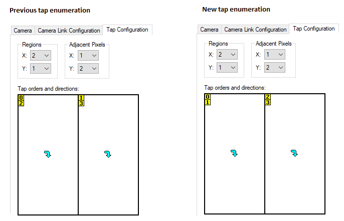
· When dealing with a DCF for a multi-tap camera that divides its image into multiple regions, if the camera sends multiple adjacent pixels per region along the Y-axis, the ordering of the regions and adjacent pixels has changed. Instead of enumerating the regions along the X-axis before the adjacent pixels along the Y-axis, the adjacent pixels along the Y-axis are enumerated before regions along the X-axis. To revert to the previous behaviour, load the DCF in Matrox Intellicam and adjust the enumeration of regions and adjacent pixels on the Tap Configuration tab of the DCF dialog. When dealing with a DCF that does not fit the above-mentioned requirement, the order has not changed.
For example, when dealing with a 4-tap DCF with the following configuration:
1.3 What’s new in MIL 10 Update 27
1.3.1 Standards compliance
The MIL 10 driver for Matrox Radient eV-CL supports the following standards:
· Camera Link® version 2.0.
· GenICamTM standard version 2.3.1.
· GenICam™ for Camera Link® (CLProtocol). Note that this requires a third party CLProtocol communication DLL provided by the camera vendor.
· GenICam™ GenCP Camera Link Module version 1.0.
1.3.2 Summary of new features
The following features are new for this release:
· Added support for all Camera Link Full 80-bit modes, including 10-tap 8-bit and 8-tap 10-bit cameras. These DCFs are produced using Matrox Intellicam.
· Added automatic hardware Bayer conversion from 8-bit or 10-bit Bayer cameras to packed or planar buffers in Host memory. The maximum line width is 8196 pixels in 8-bit and 4096 pixels in 10-bit.
· New API to latch information for each grabbed frame. See M_DATA_LATCH_* in the online help.
· New API to grab multiple frames for each grab command. This is useful when grabbing at very high frame rates. See M_GRAB_FRAME_BURST_* below.
· Added a second pulse for timer signals. See M_TIMER_DURATION2 and M_TIMER_DELAY2 below.
· Added Deserializer Setup tool in MILConfig. This tool is used to find and save in the DCF the values needed for the deserializer alignment process. It is only recommended to use this tool when using cables longer than 7 meters.
· Added the following MIL hardware-specific examples:
o DataLatch.cpp. This example is located in ...\examples\board-specific\DataLatch\c++. It demonstrates how the Data Latch API latches information at each grabbed frame (such as, timestamps and quadrature encoder positions).
o FrameBurst.cpp. This example is located in …\examples\board-specific\FrameBurst\c++. It demonstrates how the frame burst API can be used to aggregate multiple frames into each grab command.
o Clprotocol.cpp. This is a Matrox Radient eV-CL specific example. It demonstrates the use of GenICam™ for Camera Link® CLProtocol and enables the use of MdigControlFeature() and MdigInquireFeature() to control camera features (parameters), as well as enabling the use of the feature browser dialog window.
o Enumfeatures.cpp. This is a GenICam-specific example. It demonstrates how to enumerate all the features in your GenICam compliant device in a MIL application. The example is located in ...\examples\board-specific\enumfeatures\c++.
1.3.3 API enhancements
· Additions to MdigControlFeature()/MdigInquireFeature():
o M_FEATURE_ENUM_ENTRY_DISPLAY_NAME + n. Inquires the display name of the specified enumeration entry of the specified feature, where n is the index of the enumerated list. See M_FEATURE_ENUM_ENTRY_NAME in the MIL documentation.
o M_STRING_ARRAY_SIZE(). Specifies that the feature value is expressed as a string of a specified size. The M_STRING_ARRAY_SIZE() macro passes the size of the user-allocated buffer (first passed to the MdigInquireFeature's UserVarPtr parameter). See M_STRING_ARRAY_SIZE() in the MIL documentation.
· Additions to MdigControl()/MdigInquire():
v Note that the control types that can be combined with M_TIMERn are marked below. For information about M_TIMERn, refer to MdigControl() /MdigInquire().
|
M_TIMER_DELAY2 + M_TIMERn |
Sets the delay between the end of the first active portion of the timer output signal and the start of the second pulse. |
|
|
|
M_DEFAULT |
Specifies the default value. This is the same as specified in the DFC or, if not specified in the DCF, 0. |
|
Specifies the delay, in nsec. |
||
|
M_TIMER_DURATION2 + M_TIMERn |
Sets the duration for the active portion of the second pulse of the timer output signal. |
|
|
|
M_DEFAULT |
Specifies the default value. This is the same as specified in the DFC or, if not specified in the DCF, 0. |
|
Value > 0 |
Specifies the duration of the active portion of the second pulse of the timer output signal, in nsec. |
|
|
M_GRAB_FRAME_BURST_SIZE |
Specifies the number of frames grabbed into the same buffer at each grab command. The size Y of the grab buffer must be equal to (height of the frame * M_GRAB_FRAME_BURST_SIZE). |
|
|
|
M_DEFAULT |
Same as 1. |
1 <= Value <= 1023
|
Sets the number of frames grabbed. |
|
|
M_GRAB_FRAME_BURST_MAX_TIME |
Specifies the maximum amount of time to wait for all the frames to be grabbed in the multi-frame buffer. The timer starts when the first frame is grabbed. The number of frames in the buffer can be inquired using MdigGetHookInfo() with M_GRAB_FRAME_BURST_COUNT. This is useful when the camera stops sending frames and the multi-frame buffer is only partially full. |
|
|
|
M_DEFAULT |
Same as M_INFINITE. |
|
0.000008 <= Value <= 1.000000 |
Specifies the maximum amount of time to wait, in sec. |
|
|
M_INFINITE |
Specifies to wait indefinitely. |
|
|
M_GRAB_FRAME_BURST_END_TRIGGER_SOURCE
|
Specifies the signal from which a rising edge signals the end of a multi-frame sequence. This is useful to force a partially completed multi-frame buffer to complete. |
|
|
|
M_DEFAULT |
Same as M_AUX_IO0. |
M_AUX_IOn
|
Specifies to use auxiliary input signal n as the trigger source, where n is the number of the auxiliary signal. Note that the specified auxiliary signal can also be a bidirectional signal set to input (using M_IO_MODE set to M_INPUT). |
|
|
M_GRAB_FRAME_BURST_END_TRIGGER_STATE |
Enables the M_GRAB_FRAME_BURST_END_TRIGGER_SOURCE source. |
|
|
|
M_DEFAULT |
Same as M_DISABLE. |
|
M_DISABLE |
Disables the grab frame burst end trigger source. |
|
|
M_ENABLE |
Enables the grab frame burst end trigger source. |
|
· Additions to MdigHookFunction():
o You can now hook to a GenICam feature change event.
o M_GC_FEATURE_CHANGE. Hooks the function to the event that occurs when a GenICam feature value is changed on your camera. This usually occurs when a feature or a dependent feature is written.
· Additions to MdigGetHookInfo():
The following allows you to retrieve information about a GenICam SFNC-compliant event. The following information types are only available if MdigGetHookInfo() was called from a function hooked to a GenICam event using M_GC_EVENT + M_GC_FEATURE_CHANGE. In addition, the GenICam event must be enabled using MdigControlFeature(), and the message channel must be supported by your camera.
o M_GC_FEATURE_CHANGE_NAME. Retrieves the name of the GenICam feature that changed. The UserVarPtr must point to a user allocated array of type MIL_TEXT_CHAR.
o M_GC_FEATURE_CHANGE_NAME_SIZE. Retrieves the size of the name of the GenICam feature that changed. The UserVarPtr must point to a MIL_INT.
· Additions to MdigGetHookInfo():
The following allows you to retrieve information about a GenICam SFNC-compliant event. The following information types are only available if MdigGetHookInfo() was called from a function hooked to a GenICam event using M_GC_EVENT + M_GC_FEATURE_CHANGE. In addition, the GenICam event must be enabled using MdigControlFeature(), and the message channel must be supported by your camera.
o M_GC_FEATURE_CHANGE_NAME. Retrieves the name of the GenICam feature that changed. The UserVarPtr must point to a user allocated array of type MIL_TEXT_CHAR.
o M_GC_FEATURE_CHANGE_NAME_SIZE. Retrieves the size of the name of the GenICam feature that changed. The UserVarPtr must point to a MIL_INT that is the required string length +1.
|
The following allows you to retrieve information about grab frame burst events. Unless otherwise specified, you can retrieve these information types if you call this function from within a function hooked to any digitizer event using MdigHookFunction() or MdigProcess(). |
||
|
M_GRAB_FRAME_BURST_COUNT |
Retrieves the number of frames grabbed in the multi-frame buffer. |
|
|
|
Value > 0 |
Specifies the number of frames grabbed. |
|
M_GRAB_FRAME_BURST_END_SOURCE |
Retrieves the type of event that generated the end of the frame burst. Multiple events can be set at the same time. Bitwise operators must be used to verify the presence of a specific returned value. Possible return values are: |
|
|
|
M_BURST_TRIGGER |
Specifies that trigger signal generates the end of the burst sequence. To specify the source signal, use MdigControl() with M_GRAB_FRAME_BURST_END_TRIGGER_SOURCE. |
|
M_BURST_MAX_TIME |
Specifies that the frame burst has taken as much time to complete as the maximum frame burst time. To specify the maximum time for a frame burst to complete, use MdigControl with M_GRAB_FRAME_BURST_MAX_TIME. |
|
|
M_BURST_COUNT |
Specifies the number of frames that have been grabbed. To specify the number of frames in a frame burst, use MdigControl() with M_GRAB_FRAME_BURST_SIZE. |
|
|
The following allows you to retrieve information from a data latch. These information types are only available if MdigGetHookInfo() was called from a function hooked to an end of grabbed frame event using MdigHookFunction() with M_GRAB_FRAME_END or from the hook-handler function (callback function) of MdigProcess(). In addition, you must have enabled the data latch to store this information, using MdigControl() with M_DATA_LATCH_STATE. v Note that you can only use data latches in association with the MIL digitizer allocated using MdigAlloc() with M_DEV0. The following values require that you pass the UserVarPtr parameter the address of a MIL_INT64. |
||
|
M_DATA_LATCH_VALUE + M_LATCHn + M_VALUE_INDEX(i) |
Retrieves the stored data of the specified data latch. If there are multiple instances of this data (for example, your data latch is triggered at the end of each grabbed line), use + M_VALUE_INDEX(i). |
|
|
|
Specifies the stored data. |
|
|
Retrieves all the stored data of the specified data latch. |
||
|
|
Value |
Specifies all the stored data. |
|
Counts the number of items stored inside a data latch. Note that a data latch is reset at every frame event. |
||
|
|
Value |
Specifies the number of instances. Note that a data latch is reset at every frame event. |
|
Combination constant for M_DATA_LATCH_VALUE. You can add the following value to the above-mentioned value to specify the instance of the stored information to retrieve. |
|
|
M_VALUE_INDEX( MIL_INT64 IndexValue )
|
Specifies the instance of stored information to retrieve. IndexValue: Sets the instance of stored information. For example, to read the information latched when the last line finishes being grabbed for a frame, with 1024 lines, the instance would be 1023. |
This section lists all the operating systems that the Matrox Radient eV-CL driver supports.
· 32-bit and 64-bit Windows® 7.
· 32-bit and 64-bit Windows® 8.1.
· 32-bit and 64-bit Windows® 10.
In the MIL online help, the location information written at the top of examples might not be up-to-date. Use MIL Example Launcher to find an example on disk.