Matrox Morphis QxT connectors and signal names
This section serves as a reference to match Matrox Morphis QxT's connectors and auxiliary signals with MIL information, such as MIL auxiliary signal numbers.
Only those auxiliary signals that have matching MIL information are included in this section. To set/inquire the routing or state of an auxiliary signal, use MsysControl() / MsysInquire() with M_IO_... control/inquire types, respectively. To control the state of a user output signal (for example, to start or stop a process based on a calculated result), you can use MsysControl() with M_USER_BIT_... control types.
Matrox Morphis QxT has 16 acquisition paths, each with only one channel.
For information on internal connectors and a comprehensive list of all available input and output signals, refer to the board's installation and hardware reference manual.
Board connectors
Only the following connector on the Matrox Morphis QxT Digital I/O module, which interfaces with the internal digital I/O expansion connector on the base board, has auxiliary signals with matching MIL information.
|
Connector Name |
Connector Abbreviation |
Image |
Description |
|
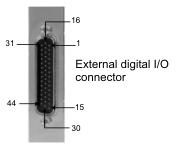
External digital I/O connector |
DBHD-44 |
|
External digital I/O connector is a high-density D-subminiature 44-pin male connector. It is used to receive and transmit auxiliary signals. |
Signal names and their matching MIL constants
The table below lists the auxiliary signals with their associated MIL information. Note that the MIL constants in this table are those to use with MIL 10 and later. If you are upgrading from a previous version of MIL, you should port your code using the conversion tables ( MilMorphisQxTIOConversionTable ) in the MIL release notes.
  Digitizer device # Digitizer device # |
Description | ||
| MIL I/O # | |||
| Pin information | |||
| Direction | |||
| User-bit information | |||
| Trigger information | |||
| Timer information | |||
| Hardware manual signal name | |||
| Digitizer device #: M_DEVn
1 |
Indicates the following. (more details...) |
||
| MIL I/O #: M_AUX_IO0 |
TTL auxiliary signal (output), which supports: user output. (more details...) |
||
| Pin information | Connector: DBHD-44 Pin: 24 | ||
| Direction |
Output |
||
| User-bit information |
MIL user-bit #: M_USER_BIT0;
|
||
| Hardware manual signal name | TTL_USER_OUT0 | ||
| MIL I/O #: M_AUX_IO1 |
TTL auxiliary signal (output), which supports: user output. (more details...) |
||
| Pin information | Connector: DBHD-44 Pin: 9 | ||
| Direction |
Output |
||
| User-bit information |
MIL user-bit #: M_USER_BIT1;
|
||
| Hardware manual signal name | TTL_USER_OUT1 | ||
| MIL I/O #: M_AUX_IO2 |
TTL auxiliary signal (output), which supports: user output. (more details...) |
||
| Pin information | Connector: DBHD-44 Pin: 39 | ||
| Direction |
Output |
||
| User-bit information |
MIL user-bit #: M_USER_BIT2;
|
||
| Hardware manual signal name | TTL_USER_OUT2 | ||
| MIL I/O #: M_AUX_IO3 |
TTL auxiliary signal (output), which supports: user output. (more details...) |
||
| Pin information | Connector: DBHD-44 Pin: 10 | ||
| Direction |
Output |
||
| User-bit information |
MIL user-bit #: M_USER_BIT3;
|
||
| Hardware manual signal name | TTL_USER_OUT3 | ||
| MIL I/O #: M_AUX_IO4 |
TTL auxiliary signal (output), which supports: user output. (more details...) |
||
| Pin information | Connector: DBHD-44 Pin: 40 | ||
| Direction |
Output |
||
| User-bit information |
MIL user-bit #: M_USER_BIT4;
|
||
| Hardware manual signal name | TTL_USER_OUT4 | ||
| MIL I/O #: M_AUX_IO5 |
TTL auxiliary signal (output), which supports: user output. (more details...) |
||
| Pin information | Connector: DBHD-44 Pin: 26 | ||
| Direction |
Output |
||
| User-bit information |
MIL user-bit #: M_USER_BIT5;
|
||
| Hardware manual signal name | TTL_USER_OUT5 | ||
| MIL I/O #: M_AUX_IO6 |
TTL auxiliary signal (output), which supports: user output. (more details...) |
||
| Pin information | Connector: DBHD-44 Pin: 41 | ||
| Direction |
Output |
||
| User-bit information |
MIL user-bit #: M_USER_BIT6;
|
||
| Hardware manual signal name | TTL_USER_OUT6 | ||
| MIL I/O #: M_AUX_IO7 |
TTL auxiliary signal (output), which supports: user output. (more details...) |
||
| Pin information | Connector: DBHD-44 Pin: 11 | ||
| Direction |
Output |
||
| User-bit information |
MIL user-bit #: M_USER_BIT7;
|
||
| Hardware manual signal name | TTL_USER_OUT7 | ||
| MIL I/O #: M_AUX_IO8 |
TTL auxiliary signal (output), which supports: user output. (more details...) |
||
| Pin information | Connector: DBHD-44 Pin: 42 | ||
| Direction |
Output |
||
| User-bit information |
MIL user-bit #: M_USER_BIT8;
|
||
| Hardware manual signal name | TTL_USER_OUT8 | ||
| MIL I/O #: M_AUX_IO9 |
TTL auxiliary signal (output), which supports: user output. (more details...) |
||
| Pin information | Connector: DBHD-44 Pin: 12 | ||
| Direction |
Output |
||
| User-bit information |
MIL user-bit #: M_USER_BIT9;
|
||
| Hardware manual signal name | TTL_USER_OUT9 | ||
| MIL I/O #: M_AUX_IO10 |
TTL auxiliary signal (output), which supports: user output. (more details...) |
||
| Pin information | Connector: DBHD-44 Pin: 28 | ||
| Direction |
Output |
||
| User-bit information |
MIL user-bit #: M_USER_BIT10;
|
||
| Hardware manual signal name | TTL_USER_OUT10 | ||
| MIL I/O #: M_AUX_IO11 |
TTL auxiliary signal (output), which supports: user output. (more details...) |
||
| Pin information | Connector: DBHD-44 Pin: 13 | ||
| Direction |
Output |
||
| User-bit information |
MIL user-bit #: M_USER_BIT11;
|
||
| Hardware manual signal name | TTL_USER_OUT11 | ||
| MIL I/O #: M_AUX_IO12 |
TTL auxiliary signal (output), which supports: user output. (more details...) |
||
| Pin information | Connector: DBHD-44 Pin: 43 | ||
| Direction |
Output |
||
| User-bit information |
MIL user-bit #: M_USER_BIT12;
|
||
| Hardware manual signal name | TTL_USER_OUT12 | ||
| MIL I/O #: M_AUX_IO13 |
TTL auxiliary signal (output), which supports: user output. (more details...) |
||
| Pin information | Connector: DBHD-44 Pin: 14 | ||
| Direction |
Output |
||
| User-bit information |
MIL user-bit #: M_USER_BIT13;
|
||
| Hardware manual signal name | TTL_USER_OUT13 | ||
| MIL I/O #: M_AUX_IO14 |
TTL auxiliary signal (output), which supports: user output. (more details...) |
||
| Pin information | Connector: DBHD-44 Pin: 44 | ||
| Direction |
Output |
||
| User-bit information |
MIL user-bit #: M_USER_BIT14;
|
||
| Hardware manual signal name | TTL_USER_OUT14 | ||
| MIL I/O #: M_AUX_IO15 |
TTL auxiliary signal (output), which supports: user output. (more details...) |
||
| Pin information | Connector: DBHD-44 Pin: 15 | ||
| Direction |
Output |
||
| User-bit information |
MIL user-bit #: M_USER_BIT15;
|
||
| Hardware manual signal name | TTL_USER_OUT15 | ||
| MIL I/O #: M_AUX_IO16 |
TTL auxiliary signal (input), which supports: user input. (more details...) |
||
| Pin information | Connector: DBHD-44 Pin: 31 | ||
| Direction |
Input |
||
| Hardware manual signal name | TTL_USER_IN0 | ||
| MIL I/O #: M_AUX_IO17 |
TTL auxiliary signal (input), which supports: user input. (more details...) |
||
| Pin information | Connector: DBHD-44 Pin: 1 | ||
| Direction |
Input |
||
| Hardware manual signal name | TTL_USER_IN1 | ||
| MIL I/O #: M_AUX_IO18 |
TTL auxiliary signal (input), which supports: user input. (more details...) |
||
| Pin information | Connector: DBHD-44 Pin: 32 | ||
| Direction |
Input |
||
| Hardware manual signal name | TTL_USER_IN2 | ||
| MIL I/O #: M_AUX_IO19 |
TTL auxiliary signal (input), which supports: user input. (more details...) |
||
| Pin information | Connector: DBHD-44 Pin: 2 | ||
| Direction |
Input |
||
| Hardware manual signal name | TTL_USER_IN3 | ||
| MIL I/O #: M_AUX_IO20 |
TTL auxiliary signal (input), which supports: user input. (more details...) |
||
| Pin information | Connector: DBHD-44 Pin: 33 | ||
| Direction |
Input |
||
| Hardware manual signal name | TTL_USER_IN4 | ||
| MIL I/O #: M_AUX_IO21 |
TTL auxiliary signal (input), which supports: user input. (more details...) |
||
| Pin information | Connector: DBHD-44 Pin: 3 | ||
| Direction |
Input |
||
| Hardware manual signal name | TTL_USER_IN5 | ||
| MIL I/O #: M_AUX_IO22 |
TTL auxiliary signal (input), which supports: user input. (more details...) |
||
| Pin information | Connector: DBHD-44 Pin: 34 | ||
| Direction |
Input |
||
| Hardware manual signal name | TTL_USER_IN6 | ||
| MIL I/O #: M_AUX_IO23 |
TTL auxiliary signal (input), which supports: user input. (more details...) |
||
| Pin information | Connector: DBHD-44 Pin: 4 | ||
| Direction |
Input |
||
| Hardware manual signal name | TTL_USER_IN7 | ||
| MIL I/O #: M_AUX_IO24 |
TTL auxiliary signal (input), which supports: user input. (more details...) |
||
| Pin information | Connector: DBHD-44 Pin: 35 | ||
| Direction |
Input |
||
| Hardware manual signal name | TTL_USER_IN8 | ||
| MIL I/O #: M_AUX_IO25 |
TTL auxiliary signal (input), which supports: user input. (more details...) |
||
| Pin information | Connector: DBHD-44 Pin: 5 | ||
| Direction |
Input |
||
| Hardware manual signal name | TTL_USER_IN9 | ||
| MIL I/O #: M_AUX_IO26 |
TTL auxiliary signal (input), which supports: user input. (more details...) |
||
| Pin information | Connector: DBHD-44 Pin: 36 | ||
| Direction |
Input |
||
| Hardware manual signal name | TTL_USER_IN10 | ||
| MIL I/O #: M_AUX_IO27 |
TTL auxiliary signal (input), which supports: user input. (more details...) |
||
| Pin information | Connector: DBHD-44 Pin: 6 | ||
| Direction |
Input |
||
| Hardware manual signal name | TTL_USER_IN11 | ||
| MIL I/O #: M_AUX_IO28 |
TTL auxiliary signal (input), which supports: user input. (more details...) |
||
| Pin information | Connector: DBHD-44 Pin: 37 | ||
| Direction |
Input |
||
| Hardware manual signal name | TTL_USER_IN12 | ||
| MIL I/O #: M_AUX_IO29 |
TTL auxiliary signal (input), which supports: user input. (more details...) |
||
| Pin information | Connector: DBHD-44 Pin: 7 | ||
| Direction |
Input |
||
| Hardware manual signal name | TTL_USER_IN13 | ||
| MIL I/O #: M_AUX_IO30 |
TTL auxiliary signal (input), which supports: user input. (more details...) |
||
| Pin information | Connector: DBHD-44 Pin: 38 | ||
| Direction |
Input |
||
| Hardware manual signal name | TTL_USER_IN14 | ||
| MIL I/O #: M_AUX_IO31 |
TTL auxiliary signal (input), which supports: user input. (more details...) |
||
| Pin information | Connector: DBHD-44 Pin: 8 | ||
| Direction |
Input |
||
| Hardware manual signal name | TTL_USER_IN15 | ||
1 Note that these are shared auxiliary signals between digitizers. If used by one digitizer, they can be simultaneously used by all others that share this auxiliary signal. The value of n can be between 0 and 15, because those signals can be shared among 16 different acquisition paths. Note that, shared output signals can be controlled by different digitizers, so you must ensure that only one digitizer is driving the output.