3D reconstruction using laser line profiling overview
The MIL 3D Reconstruction module allows you to extract 3D information from 2D images of an object taken using a 3D reconstruction setup built for laser line profiling. From the grabbed images of objects passing through a sheet of light or laser plane, the module can create a cloud of 3D points and generate depth maps.
A basic laser line profiling setup consists of a device projecting a sheet of light (usually a laser diode), a camera, and a mechanism to move the object under the laser plane (for example, a conveyor belt). An object is then moved at a known speed and on a straight path perpendicular to the laser plane. As the object moves through the laser plane, the camera is used to grab images of the intersection of that laser plane with the object.
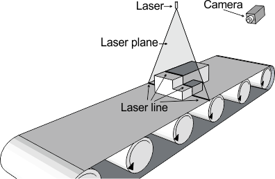
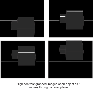
As a result, multiple images are grabbed such that the laser line in each image represents a slice of the object being scanned. The incidence of the laser light on the object, at an angle from the optical axis of the camera, leads to an image whereby the line of laser light is deformed. From the position of the displaced laser line, the 3D reconstruction module can obtain height (depth) information for the slice of the object.
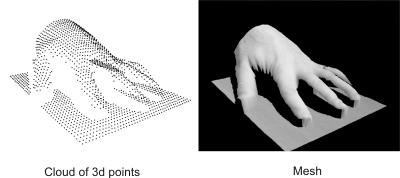
When your laser line profiling setup is fully calibrated, including camera calibration, passing an object through a sheet of light or laser plane will result in a cloud of 3D points. The cloud of points is a 3D representation of the object's surface. You can further process and refine the 3D points with third-party tools to generate a mesh.
With a fully calibrated setup, you can add additional cameras and/or lasers. The additional cameras could be used to increase the resolution of the sheet of light data or to overcome the occlusion of sections of the scanned object due to the camera angle and placement. Multiple cameras or multiple lasers creates multiple point clouds.
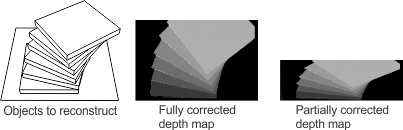
From the cloud(s) of points, the 3D reconstruction module can generate a fully corrected depth map and an intensity map. A depth map is an image whereby each pixel's intensity represent its depth in the world. An intensity map is an image where each pixel's intensity is the brightness or reflectance of the scanned object. If you include camera calibration information, the generated depth map is fully corrected, which means it is visually corrected to represent the actual shape and height of the object. You can use the fully calibrated depth map to calculate the volume and other statistics of the object, or as an input to MIL 2D modules to find defects.
If you are only interested in the depth of an object and not its shape, the 3D reconstruction module can generate a partially corrected depth map, which is corrected for depth, but not for camera distortion or shape. In this case, no camera calibration is used in the generation of the depth map.