Matrox Concord PoE with ToE connectors and signal names
- See also

 Previous
- Next

This section serves as a reference to match Matrox Concord PoE with ToE's connectors and auxiliary signals with MIL information, such as MIL auxiliary signal numbers. To set/inquire all the settings for this board's auxiliary signals (for example, signal routing and timer settings), use MsysControl() / MsysInquire(), respectively.
Auxiliary I/O signals can have one or more functionalities (for example, outputting the state of an I/O command register bit, timer output, or user output, depending on the signal). Their possible functionalities are described in their description in the pinout table below. Note that, there is no limit to the number of events that can be triggered simultaneously using the auxiliary input signals, nor is there a restriction on which auxiliary signal can be used to trigger the event.
Only those auxiliary signals that have matching MIL information are included in this section. For information on internal connectors and a comprehensive list of all available input and output signals, refer to the board's installation and hardware reference manual.
Board connectors
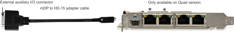
The Matrox Concord PoE with ToE board provides an external auxiliary I/O connector and Gigabit Ethernet connectors.
Only the following connectors have auxiliary signals with matching MIL information.
|
Connector Name |
Connector Abbreviation |
Image |
Description |
|
External auxiliary I/O connector |
HD-15 |

|
The external auxiliary I/O connectors is used to transmit/receive auxiliary signals from the Advanced I/O engine. |
Signal names and their matching MIL constants
The table below lists the auxiliary signals with their associated MIL information.
|
|
Description | ||
| MIL I/O # | |||
| Pin information | |||
| Direction | |||
| User-bit information | |||
| Trigger information | |||
| Timer information | |||
| Hardware manual signal name | |||
|
Indicates the following. (summarize)Indicates the following. (more details...) |
|||
|
Opto-isolated auxiliary signal 0 (output), which supports: user output, timer output, and receiving the state of an I/O command register bit. (summarize)Opto-isolated auxiliary signal 0 (output), which supports: user output, timer output, and receiving the state of an I/O command register bit. (more details...) |
|||
| Pin information | Connector: HD-15 Pin: 12+, 11- | ||
| Direction |
Output |
||
| User-bit information |
MIL user-bit #: M_USER_BIT0;
|
||
| Timer information | Timer: M_TIMERn | ||
| Hardware manual signal name | AUX_OPTOIND_OUT0 | ||
|
Opto-isolated auxiliary signal 1 (output), which supports: user output, timer output, and outputting the state of an I/O command register bit. (summarize)Opto-isolated auxiliary signal 1 (output), which supports: user output, timer output, and outputting the state of an I/O command register bit. (more details...) |
|||
| Pin information | Connector: HD-15 Pin: 6+, 1- | ||
| Direction |
Output |
||
| User-bit information |
MIL user-bit #: M_USER_BIT1;
|
||
| Timer information | Timer: M_TIMERn | ||
| Hardware manual signal name | AUX_OPTOIND_OUT1 | ||
|
Opto-isolated auxiliary signal 2 (input), which supports: user input, I/O command list counter source, timer clock, timer arm, reference latch trigger, quadrature input bit 0 or 1, or quadrature decoder counter reset source. (summarize)Opto-isolated auxiliary signal 2 (input), which supports: user input, I/O command list counter source, timer clock, timer arm, reference latch trigger, quadrature input bit 0 or 1, or quadrature decoder counter reset source. (more details...) |
|||
| Pin information | Connector: HD-15 Pin: 5+, 4 (AUX_OPTOIND_IN_COM_2-3) | ||
| Direction |
Input |
||
| Timer information | Timer: M_TIMERn | ||
| Hardware manual signal name | AUX_OPTOIND_IN2 | ||
|
Opto-isolated auxiliary signal 3 (input), which supports: user input, I/O command list counter source, timer clock, timer arm, reference latch trigger, quadrature input bit 0 or 1, or quadrature decoder counter reset source. (summarize)Opto-isolated auxiliary signal 3 (input), which supports: user input, I/O command list counter source, timer clock, timer arm, reference latch trigger, quadrature input bit 0 or 1, or quadrature decoder counter reset source. (more details...) |
|||
| Pin information | Connector: HD-15 Pin: 3+, 4 (AUX_OPTOIND_IN_COM_2-3) | ||
| Direction |
Input |
||
| Timer information | Timer: M_TIMERn | ||
| Hardware manual signal name | AUX_OPTOIND_IN3 | ||
|
Opto-isolated auxiliary signal 4 (input), which supports: user input, I/O command list counter source, timer clock, timer arm, reference latch trigger, quadrature input bit 0 or 1, or quadrature decoder counter reset source. (summarize)Opto-isolated auxiliary signal 4 (input), which supports: user input, I/O command list counter source, timer clock, timer arm, reference latch trigger, quadrature input bit 0 or 1, or quadrature decoder counter reset source. (more details...) |
|||
| Pin information | Connector: HD-15 Pin: 9+, 8 (AUX_OPTOIND_IN_COM_4-5) | ||
| Direction |
Input |
||
| Timer information | Timer: M_TIMERn | ||
| Hardware manual signal name | AUX_OPTOIND_IN4 | ||
|
Opto-isolated auxiliary signal 5 (input), which supports: user input, I/O command list counter source, timer clock, timer arm, reference latch trigger, quadrature input bit 0 or 1, or quadrature decoder counter reset source. (summarize)Opto-isolated auxiliary signal 5 (input), which supports: user input, I/O command list counter source, timer clock, timer arm, reference latch trigger, quadrature input bit 0 or 1, or quadrature decoder counter reset source. (more details...) |
|||
| Pin information | Connector: HD-15 Pin: 2+, 8 (AUX_OPTOIND_IN_COM_4-5) | ||
| Direction |
Input |
||
| Timer information | Timer: M_TIMERn | ||
| Hardware manual signal name | AUX_OPTOIND_IN5 | ||
|
Opto-isolated auxiliary signal 6 (input), which supports: user input, I/O command list counter source, timer clock, timer arm, reference latch trigger, quadrature input bit 0 or 1, or quadrature decoder counter reset source. (summarize)Opto-isolated auxiliary signal 6 (input), which supports: user input, I/O command list counter source, timer clock, timer arm, reference latch trigger, quadrature input bit 0 or 1, or quadrature decoder counter reset source. (more details...) |
|||
| Pin information | Connector: HD-15 Pin: 15+, 14 (AUX_OPTOIND_IN_COM_6-7) | ||
| Direction |
Input |
||
| Timer information | Timer: M_TIMERn | ||
| Hardware manual signal name | AUX_OPTOIND_IN6 | ||
|
Opto-isolated auxiliary signal 7 (input), which supports: user input, I/O command list counter source, timer clock, timer arm, reference latch trigger, quadrature input bit 0 or 1, or quadrature decoder counter reset source. (summarize)Opto-isolated auxiliary signal 7 (input), which supports: user input, I/O command list counter source, timer clock, timer arm, reference latch trigger, quadrature input bit 0 or 1, or quadrature decoder counter reset source. (more details...) |
|||
| Pin information | Connector: HD-15 Pin: 13+, 14 (AUX_OPTOIND_IN_COM_6-7) | ||
| Direction |
Input |
||
| Timer information | Timer: M_TIMERn | ||
| Hardware manual signal name | AUX_OPTOIND_IN7 | ||
|
|
Description | ||
| MIL I/O # | |||
| Pin information | |||
| Direction | |||
| User-bit information | |||
| Trigger information | |||
| Timer information | |||
| Hardware manual signal name | |||
|
Indicates the following. (summarize)Indicates the following. (more details...) |
|||
|
Opto-isolated auxiliary signal 0 (output), which supports: user output, timer output, and receiving the state of an I/O command register bit. (summarize)Opto-isolated auxiliary signal 0 (output), which supports: user output, timer output, and receiving the state of an I/O command register bit. (more details...) |
|||
| Pin information | Connector: HD-15 Pin: 12+, 11- | ||
| Direction |
Output |
||
| User-bit information |
MIL user-bit #: M_USER_BIT0;
|
||
| Timer information | Timer: M_TIMERn | ||
| Hardware manual signal name | AUX_OPTOIND_OUT0 | ||
|
Opto-isolated auxiliary signal 1 (output), which supports: user output, timer output, and outputting the state of an I/O command register bit. (summarize)Opto-isolated auxiliary signal 1 (output), which supports: user output, timer output, and outputting the state of an I/O command register bit. (more details...) |
|||
| Pin information | Connector: HD-15 Pin: 6+, 1- | ||
| Direction |
Output |
||
| User-bit information |
MIL user-bit #: M_USER_BIT1;
|
||
| Timer information | Timer: M_TIMERn | ||
| Hardware manual signal name | AUX_OPTOIND_OUT1 | ||
|
|
Description | ||
| MIL I/O # | |||
| Pin information | |||
| Direction | |||
| User-bit information | |||
| Trigger information | |||
| Timer information | |||
| Hardware manual signal name | |||
|
|
Description | ||
| MIL I/O # | |||
| Pin information | |||
| Direction | |||
| User-bit information | |||
| Trigger information | |||
| Timer information | |||
| Hardware manual signal name | |||
|
Indicates the following. (summarize)Indicates the following. (more details...) |
|||
|
Opto-isolated auxiliary signal 0 (output), which supports: user output, timer output, and receiving the state of an I/O command register bit. (summarize)Opto-isolated auxiliary signal 0 (output), which supports: user output, timer output, and receiving the state of an I/O command register bit. (more details...) |
|||
| Pin information | Connector: HD-15 Pin: 12+, 11- | ||
| Direction |
Output |
||
| User-bit information |
MIL user-bit #: M_USER_BIT0;
|
||
| Timer information | Timer: M_TIMERn | ||
| Hardware manual signal name | AUX_OPTOIND_OUT0 | ||
|
Opto-isolated auxiliary signal 1 (output), which supports: user output, timer output, and outputting the state of an I/O command register bit. (summarize)Opto-isolated auxiliary signal 1 (output), which supports: user output, timer output, and outputting the state of an I/O command register bit. (more details...) |
|||
| Pin information | Connector: HD-15 Pin: 6+, 1- | ||
| Direction |
Output |
||
| User-bit information |
MIL user-bit #: M_USER_BIT1;
|
||
| Timer information | Timer: M_TIMERn | ||
| Hardware manual signal name | AUX_OPTOIND_OUT1 | ||
|
Opto-isolated auxiliary signal 2 (input), which supports: user input, I/O command list counter source, timer clock, timer arm, reference latch trigger, quadrature input bit 0 or 1, or quadrature decoder counter reset source. (summarize)Opto-isolated auxiliary signal 2 (input), which supports: user input, I/O command list counter source, timer clock, timer arm, reference latch trigger, quadrature input bit 0 or 1, or quadrature decoder counter reset source. (more details...) |
|||
| Pin information | Connector: HD-15 Pin: 5+, 4 (AUX_OPTOIND_IN_COM_2-3) | ||
| Direction |
Input |
||
| Timer information | Timer: M_TIMERn | ||
| Hardware manual signal name | AUX_OPTOIND_IN2 | ||
|
Opto-isolated auxiliary signal 3 (input), which supports: user input, I/O command list counter source, timer clock, timer arm, reference latch trigger, quadrature input bit 0 or 1, or quadrature decoder counter reset source. (summarize)Opto-isolated auxiliary signal 3 (input), which supports: user input, I/O command list counter source, timer clock, timer arm, reference latch trigger, quadrature input bit 0 or 1, or quadrature decoder counter reset source. (more details...) |
|||
| Pin information | Connector: HD-15 Pin: 3+, 4 (AUX_OPTOIND_IN_COM_2-3) | ||
| Direction |
Input |
||
| Timer information | Timer: M_TIMERn | ||
| Hardware manual signal name | AUX_OPTOIND_IN3 | ||
|
Opto-isolated auxiliary signal 4 (input), which supports: user input, I/O command list counter source, timer clock, timer arm, reference latch trigger, quadrature input bit 0 or 1, or quadrature decoder counter reset source. (summarize)Opto-isolated auxiliary signal 4 (input), which supports: user input, I/O command list counter source, timer clock, timer arm, reference latch trigger, quadrature input bit 0 or 1, or quadrature decoder counter reset source. (more details...) |
|||
| Pin information | Connector: HD-15 Pin: 9+, 8 (AUX_OPTOIND_IN_COM_4-5) | ||
| Direction |
Input |
||
| Timer information | Timer: M_TIMERn | ||
| Hardware manual signal name | AUX_OPTOIND_IN4 | ||
|
Opto-isolated auxiliary signal 5 (input), which supports: user input, I/O command list counter source, timer clock, timer arm, reference latch trigger, quadrature input bit 0 or 1, or quadrature decoder counter reset source. (summarize)Opto-isolated auxiliary signal 5 (input), which supports: user input, I/O command list counter source, timer clock, timer arm, reference latch trigger, quadrature input bit 0 or 1, or quadrature decoder counter reset source. (more details...) |
|||
| Pin information | Connector: HD-15 Pin: 2+, 8 (AUX_OPTOIND_IN_COM_4-5) | ||
| Direction |
Input |
||
| Timer information | Timer: M_TIMERn | ||
| Hardware manual signal name | AUX_OPTOIND_IN5 | ||
|
Opto-isolated auxiliary signal 6 (input), which supports: user input, I/O command list counter source, timer clock, timer arm, reference latch trigger, quadrature input bit 0 or 1, or quadrature decoder counter reset source. (summarize)Opto-isolated auxiliary signal 6 (input), which supports: user input, I/O command list counter source, timer clock, timer arm, reference latch trigger, quadrature input bit 0 or 1, or quadrature decoder counter reset source. (more details...) |
|||
| Pin information | Connector: HD-15 Pin: 15+, 14 (AUX_OPTOIND_IN_COM_6-7) | ||
| Direction |
Input |
||
| Timer information | Timer: M_TIMERn | ||
| Hardware manual signal name | AUX_OPTOIND_IN6 | ||
|
Opto-isolated auxiliary signal 7 (input), which supports: user input, I/O command list counter source, timer clock, timer arm, reference latch trigger, quadrature input bit 0 or 1, or quadrature decoder counter reset source. (summarize)Opto-isolated auxiliary signal 7 (input), which supports: user input, I/O command list counter source, timer clock, timer arm, reference latch trigger, quadrature input bit 0 or 1, or quadrature decoder counter reset source. (more details...) |
|||
| Pin information | Connector: HD-15 Pin: 13+, 14 (AUX_OPTOIND_IN_COM_6-7) | ||
| Direction |
Input |
||
| Timer information | Timer: M_TIMERn | ||
| Hardware manual signal name | AUX_OPTOIND_IN7 | ||
|
|
Description | ||
| MIL I/O # | |||
| Pin information | |||
| Direction | |||
| User-bit information | |||
| Trigger information | |||
| Timer information | |||
| Hardware manual signal name | |||
|
|
Description | ||
| Pin | |||
| MIL I/O information | |||
| Direction | |||
| User-bit information | |||
| Trigger information | |||
| Timer information | |||
| Hardware manual signal name | |||
|
Indicates the following. (summarize)Indicates the following. (more details...) |
|||
|
Opto-isolated auxiliary signal 5 (input), which supports: user input, I/O command list counter source, timer clock, timer arm, reference latch trigger, quadrature input bit 0 or 1, or quadrature decoder counter reset source. (summarize)Opto-isolated auxiliary signal 5 (input), which supports: user input, I/O command list counter source, timer clock, timer arm, reference latch trigger, quadrature input bit 0 or 1, or quadrature decoder counter reset source. (more details...) |
|||
| MIL I/O information | MIL I/O #:M_AUX_IO5; | ||
| Direction |
Input |
||
| Timer information | Timer: M_TIMERn | ||
| Hardware manual signal name | AUX_OPTOIND_IN5 | ||
|
Opto-isolated auxiliary signal 3 (input), which supports: user input, I/O command list counter source, timer clock, timer arm, reference latch trigger, quadrature input bit 0 or 1, or quadrature decoder counter reset source. (summarize)Opto-isolated auxiliary signal 3 (input), which supports: user input, I/O command list counter source, timer clock, timer arm, reference latch trigger, quadrature input bit 0 or 1, or quadrature decoder counter reset source. (more details...) |
|||
| MIL I/O information | MIL I/O #:M_AUX_IO3; | ||
| Direction |
Input |
||
| Timer information | Timer: M_TIMERn | ||
| Hardware manual signal name | AUX_OPTOIND_IN3 | ||
|
Opto-isolated auxiliary signal 2 (input), which supports: user input, I/O command list counter source, timer clock, timer arm, reference latch trigger, quadrature input bit 0 or 1, or quadrature decoder counter reset source. (summarize)Opto-isolated auxiliary signal 2 (input), which supports: user input, I/O command list counter source, timer clock, timer arm, reference latch trigger, quadrature input bit 0 or 1, or quadrature decoder counter reset source. (more details...) |
|||
| MIL I/O information | MIL I/O #:M_AUX_IO2; | ||
| Direction |
Input |
||
| Timer information | Timer: M_TIMERn | ||
| Hardware manual signal name | AUX_OPTOIND_IN2 | ||
|
Opto-isolated auxiliary signal 1 (output), which supports: user output, timer output, and outputting the state of an I/O command register bit. (summarize)Opto-isolated auxiliary signal 1 (output), which supports: user output, timer output, and outputting the state of an I/O command register bit. (more details...) |
|||
| MIL I/O information | MIL I/O #:M_AUX_IO1; | ||
| Direction |
Output |
||
| User-bit information |
MIL user-bit #: M_USER_BIT1;
|
||
| Timer information | Timer: M_TIMERn | ||
| Hardware manual signal name | AUX_OPTOIND_OUT1 | ||
|
Opto-isolated auxiliary signal 4 (input), which supports: user input, I/O command list counter source, timer clock, timer arm, reference latch trigger, quadrature input bit 0 or 1, or quadrature decoder counter reset source. (summarize)Opto-isolated auxiliary signal 4 (input), which supports: user input, I/O command list counter source, timer clock, timer arm, reference latch trigger, quadrature input bit 0 or 1, or quadrature decoder counter reset source. (more details...) |
|||
| MIL I/O information | MIL I/O #:M_AUX_IO4; | ||
| Direction |
Input |
||
| Timer information | Timer: M_TIMERn | ||
| Hardware manual signal name | AUX_OPTOIND_IN4 | ||
|
Opto-isolated auxiliary signal 0 (output), which supports: user output, timer output, and receiving the state of an I/O command register bit. (summarize)Opto-isolated auxiliary signal 0 (output), which supports: user output, timer output, and receiving the state of an I/O command register bit. (more details...) |
|||
| MIL I/O information | MIL I/O #:M_AUX_IO0; | ||
| Direction |
Output |
||
| User-bit information |
MIL user-bit #: M_USER_BIT0;
|
||
| Timer information | Timer: M_TIMERn | ||
| Hardware manual signal name | AUX_OPTOIND_OUT0 | ||
|
Opto-isolated auxiliary signal 7 (input), which supports: user input, I/O command list counter source, timer clock, timer arm, reference latch trigger, quadrature input bit 0 or 1, or quadrature decoder counter reset source. (summarize)Opto-isolated auxiliary signal 7 (input), which supports: user input, I/O command list counter source, timer clock, timer arm, reference latch trigger, quadrature input bit 0 or 1, or quadrature decoder counter reset source. (more details...) |
|||
| MIL I/O information | MIL I/O #:M_AUX_IO7; | ||
| Direction |
Input |
||
| Timer information | Timer: M_TIMERn | ||
| Hardware manual signal name | AUX_OPTOIND_IN7 | ||
|
Opto-isolated auxiliary signal 6 (input), which supports: user input, I/O command list counter source, timer clock, timer arm, reference latch trigger, quadrature input bit 0 or 1, or quadrature decoder counter reset source. (summarize)Opto-isolated auxiliary signal 6 (input), which supports: user input, I/O command list counter source, timer clock, timer arm, reference latch trigger, quadrature input bit 0 or 1, or quadrature decoder counter reset source. (more details...) |
|||
| MIL I/O information | MIL I/O #:M_AUX_IO6; | ||
| Direction |
Input |
||
| Timer information | Timer: M_TIMERn | ||
| Hardware manual signal name | AUX_OPTOIND_IN6 | ||
|
|
Description | ||
| Pin | |||
| MIL I/O information | |||
| Direction | |||
| User-bit information | |||
| Trigger information | |||
| Timer information | |||
| Hardware manual signal name | |||
|
Indicates the following. (summarize)Indicates the following. (more details...) |
|||
|
Opto-isolated auxiliary signal 5 (input), which supports: user input, I/O command list counter source, timer clock, timer arm, reference latch trigger, quadrature input bit 0 or 1, or quadrature decoder counter reset source. (summarize)Opto-isolated auxiliary signal 5 (input), which supports: user input, I/O command list counter source, timer clock, timer arm, reference latch trigger, quadrature input bit 0 or 1, or quadrature decoder counter reset source. (more details...) |
|||
| MIL I/O information | MIL I/O #:M_AUX_IO5; | ||
| Direction |
Input |
||
| Timer information | Timer: M_TIMERn | ||
| Hardware manual signal name | AUX_OPTOIND_IN5 | ||
|
Opto-isolated auxiliary signal 3 (input), which supports: user input, I/O command list counter source, timer clock, timer arm, reference latch trigger, quadrature input bit 0 or 1, or quadrature decoder counter reset source. (summarize)Opto-isolated auxiliary signal 3 (input), which supports: user input, I/O command list counter source, timer clock, timer arm, reference latch trigger, quadrature input bit 0 or 1, or quadrature decoder counter reset source. (more details...) |
|||
| MIL I/O information | MIL I/O #:M_AUX_IO3; | ||
| Direction |
Input |
||
| Timer information | Timer: M_TIMERn | ||
| Hardware manual signal name | AUX_OPTOIND_IN3 | ||
|
Opto-isolated auxiliary signal 2 (input), which supports: user input, I/O command list counter source, timer clock, timer arm, reference latch trigger, quadrature input bit 0 or 1, or quadrature decoder counter reset source. (summarize)Opto-isolated auxiliary signal 2 (input), which supports: user input, I/O command list counter source, timer clock, timer arm, reference latch trigger, quadrature input bit 0 or 1, or quadrature decoder counter reset source. (more details...) |
|||
| MIL I/O information | MIL I/O #:M_AUX_IO2; | ||
| Direction |
Input |
||
| Timer information | Timer: M_TIMERn | ||
| Hardware manual signal name | AUX_OPTOIND_IN2 | ||
|
Opto-isolated auxiliary signal 4 (input), which supports: user input, I/O command list counter source, timer clock, timer arm, reference latch trigger, quadrature input bit 0 or 1, or quadrature decoder counter reset source. (summarize)Opto-isolated auxiliary signal 4 (input), which supports: user input, I/O command list counter source, timer clock, timer arm, reference latch trigger, quadrature input bit 0 or 1, or quadrature decoder counter reset source. (more details...) |
|||
| MIL I/O information | MIL I/O #:M_AUX_IO4; | ||
| Direction |
Input |
||
| Timer information | Timer: M_TIMERn | ||
| Hardware manual signal name | AUX_OPTOIND_IN4 | ||
|
Opto-isolated auxiliary signal 7 (input), which supports: user input, I/O command list counter source, timer clock, timer arm, reference latch trigger, quadrature input bit 0 or 1, or quadrature decoder counter reset source. (summarize)Opto-isolated auxiliary signal 7 (input), which supports: user input, I/O command list counter source, timer clock, timer arm, reference latch trigger, quadrature input bit 0 or 1, or quadrature decoder counter reset source. (more details...) |
|||
| MIL I/O information | MIL I/O #:M_AUX_IO7; | ||
| Direction |
Input |
||
| Timer information | Timer: M_TIMERn | ||
| Hardware manual signal name | AUX_OPTOIND_IN7 | ||
|
Opto-isolated auxiliary signal 6 (input), which supports: user input, I/O command list counter source, timer clock, timer arm, reference latch trigger, quadrature input bit 0 or 1, or quadrature decoder counter reset source. (summarize)Opto-isolated auxiliary signal 6 (input), which supports: user input, I/O command list counter source, timer clock, timer arm, reference latch trigger, quadrature input bit 0 or 1, or quadrature decoder counter reset source. (more details...) |
|||
| MIL I/O information | MIL I/O #:M_AUX_IO6; | ||
| Direction |
Input |
||
| Timer information | Timer: M_TIMERn | ||
| Hardware manual signal name | AUX_OPTOIND_IN6 | ||
|
|
Description | ||
| Pin | |||
| MIL I/O information | |||
| Direction | |||
| User-bit information | |||
| Trigger information | |||
| Timer information | |||
| Hardware manual signal name | |||
|
Indicates the following. (summarize)Indicates the following. (more details...) |
|||
|
Opto-isolated auxiliary signal 1 (output), which supports: user output, timer output, and outputting the state of an I/O command register bit. (summarize)Opto-isolated auxiliary signal 1 (output), which supports: user output, timer output, and outputting the state of an I/O command register bit. (more details...) |
|||
| MIL I/O information | MIL I/O #:M_AUX_IO1; | ||
| Direction |
Output |
||
| User-bit information |
MIL user-bit #: M_USER_BIT1;
|
||
| Timer information | Timer: M_TIMERn | ||
| Hardware manual signal name | AUX_OPTOIND_OUT1 | ||
|
Opto-isolated auxiliary signal 0 (output), which supports: user output, timer output, and receiving the state of an I/O command register bit. (summarize)Opto-isolated auxiliary signal 0 (output), which supports: user output, timer output, and receiving the state of an I/O command register bit. (more details...) |
|||
| MIL I/O information | MIL I/O #:M_AUX_IO0; | ||
| Direction |
Output |
||
| User-bit information |
MIL user-bit #: M_USER_BIT0;
|
||
| Timer information | Timer: M_TIMERn | ||
| Hardware manual signal name | AUX_OPTOIND_OUT0 | ||
|
|
Description | ||
| Pin | |||
| MIL I/O information | |||
| Direction | |||
| User-bit information | |||
| Trigger information | |||
| Timer information | |||
| Hardware manual signal name | |||
|
|
Description | ||
| Pin | |||
| MIL I/O information | |||
| Direction | |||
| User-bit information | |||
| Trigger information | |||
| Timer information | |||
| Hardware manual signal name | |||
|
Indicates the following. (summarize)Indicates the following. (more details...) |
|||
|
Opto-isolated auxiliary signal 5 (input), which supports: user input, I/O command list counter source, timer clock, timer arm, reference latch trigger, quadrature input bit 0 or 1, or quadrature decoder counter reset source. (summarize)Opto-isolated auxiliary signal 5 (input), which supports: user input, I/O command list counter source, timer clock, timer arm, reference latch trigger, quadrature input bit 0 or 1, or quadrature decoder counter reset source. (more details...) |
|||
| MIL I/O information | MIL I/O #:M_AUX_IO5; | ||
| Direction |
Input |
||
| Timer information | Timer: M_TIMERn | ||
| Hardware manual signal name | AUX_OPTOIND_IN5 | ||
|
Opto-isolated auxiliary signal 3 (input), which supports: user input, I/O command list counter source, timer clock, timer arm, reference latch trigger, quadrature input bit 0 or 1, or quadrature decoder counter reset source. (summarize)Opto-isolated auxiliary signal 3 (input), which supports: user input, I/O command list counter source, timer clock, timer arm, reference latch trigger, quadrature input bit 0 or 1, or quadrature decoder counter reset source. (more details...) |
|||
| MIL I/O information | MIL I/O #:M_AUX_IO3; | ||
| Direction |
Input |
||
| Timer information | Timer: M_TIMERn | ||
| Hardware manual signal name | AUX_OPTOIND_IN3 | ||
|
Opto-isolated auxiliary signal 2 (input), which supports: user input, I/O command list counter source, timer clock, timer arm, reference latch trigger, quadrature input bit 0 or 1, or quadrature decoder counter reset source. (summarize)Opto-isolated auxiliary signal 2 (input), which supports: user input, I/O command list counter source, timer clock, timer arm, reference latch trigger, quadrature input bit 0 or 1, or quadrature decoder counter reset source. (more details...) |
|||
| MIL I/O information | MIL I/O #:M_AUX_IO2; | ||
| Direction |
Input |
||
| Timer information | Timer: M_TIMERn | ||
| Hardware manual signal name | AUX_OPTOIND_IN2 | ||
|
Opto-isolated auxiliary signal 1 (output), which supports: user output, timer output, and outputting the state of an I/O command register bit. (summarize)Opto-isolated auxiliary signal 1 (output), which supports: user output, timer output, and outputting the state of an I/O command register bit. (more details...) |
|||
| MIL I/O information | MIL I/O #:M_AUX_IO1; | ||
| Direction |
Output |
||
| User-bit information |
MIL user-bit #: M_USER_BIT1;
|
||
| Timer information | Timer: M_TIMERn | ||
| Hardware manual signal name | AUX_OPTOIND_OUT1 | ||
|
Opto-isolated auxiliary signal 4 (input), which supports: user input, I/O command list counter source, timer clock, timer arm, reference latch trigger, quadrature input bit 0 or 1, or quadrature decoder counter reset source. (summarize)Opto-isolated auxiliary signal 4 (input), which supports: user input, I/O command list counter source, timer clock, timer arm, reference latch trigger, quadrature input bit 0 or 1, or quadrature decoder counter reset source. (more details...) |
|||
| MIL I/O information | MIL I/O #:M_AUX_IO4; | ||
| Direction |
Input |
||
| Timer information | Timer: M_TIMERn | ||
| Hardware manual signal name | AUX_OPTOIND_IN4 | ||
|
Opto-isolated auxiliary signal 0 (output), which supports: user output, timer output, and receiving the state of an I/O command register bit. (summarize)Opto-isolated auxiliary signal 0 (output), which supports: user output, timer output, and receiving the state of an I/O command register bit. (more details...) |
|||
| MIL I/O information | MIL I/O #:M_AUX_IO0; | ||
| Direction |
Output |
||
| User-bit information |
MIL user-bit #: M_USER_BIT0;
|
||
| Timer information | Timer: M_TIMERn | ||
| Hardware manual signal name | AUX_OPTOIND_OUT0 | ||
|
Opto-isolated auxiliary signal 7 (input), which supports: user input, I/O command list counter source, timer clock, timer arm, reference latch trigger, quadrature input bit 0 or 1, or quadrature decoder counter reset source. (summarize)Opto-isolated auxiliary signal 7 (input), which supports: user input, I/O command list counter source, timer clock, timer arm, reference latch trigger, quadrature input bit 0 or 1, or quadrature decoder counter reset source. (more details...) |
|||
| MIL I/O information | MIL I/O #:M_AUX_IO7; | ||
| Direction |
Input |
||
| Timer information | Timer: M_TIMERn | ||
| Hardware manual signal name | AUX_OPTOIND_IN7 | ||
|
Opto-isolated auxiliary signal 6 (input), which supports: user input, I/O command list counter source, timer clock, timer arm, reference latch trigger, quadrature input bit 0 or 1, or quadrature decoder counter reset source. (summarize)Opto-isolated auxiliary signal 6 (input), which supports: user input, I/O command list counter source, timer clock, timer arm, reference latch trigger, quadrature input bit 0 or 1, or quadrature decoder counter reset source. (more details...) |
|||
| MIL I/O information | MIL I/O #:M_AUX_IO6; | ||
| Direction |
Input |
||
| Timer information | Timer: M_TIMERn | ||
| Hardware manual signal name | AUX_OPTOIND_IN6 | ||
|
|
Description | ||
| Pin | |||
| MIL I/O information | |||
| Direction | |||
| User-bit information | |||
| Trigger information | |||
| Timer information | |||
| Hardware manual signal name | |||
|
|
Description | |
| MIL I/O information | ||
| Pin information | ||
| Direction | ||
| User-bit information | ||
| Trigger information | ||
| Timer information | ||
|
Opto-isolated auxiliary signal 2 (input), which supports: user input, I/O command list counter source, timer clock, timer arm, reference latch trigger, quadrature input bit 0 or 1, or quadrature decoder counter reset source. (summarize)Opto-isolated auxiliary signal 2 (input), which supports: user input, I/O command list counter source, timer clock, timer arm, reference latch trigger, quadrature input bit 0 or 1, or quadrature decoder counter reset source. (more details...) |
||
| MIL I/O information | MIL I/O #:M_AUX_IO2; | |
| Pin information | Connector: HD-15 Pin: 5+, 4 (AUX_OPTOIND_IN_COM_2-3) | |
| Direction |
Input |
|
| Timer information | Timer: M_TIMERn | |
|
Opto-isolated auxiliary signal 3 (input), which supports: user input, I/O command list counter source, timer clock, timer arm, reference latch trigger, quadrature input bit 0 or 1, or quadrature decoder counter reset source. (summarize)Opto-isolated auxiliary signal 3 (input), which supports: user input, I/O command list counter source, timer clock, timer arm, reference latch trigger, quadrature input bit 0 or 1, or quadrature decoder counter reset source. (more details...) |
||
| MIL I/O information | MIL I/O #:M_AUX_IO3; | |
| Pin information | Connector: HD-15 Pin: 3+, 4 (AUX_OPTOIND_IN_COM_2-3) | |
| Direction |
Input |
|
| Timer information | Timer: M_TIMERn | |
|
Opto-isolated auxiliary signal 4 (input), which supports: user input, I/O command list counter source, timer clock, timer arm, reference latch trigger, quadrature input bit 0 or 1, or quadrature decoder counter reset source. (summarize)Opto-isolated auxiliary signal 4 (input), which supports: user input, I/O command list counter source, timer clock, timer arm, reference latch trigger, quadrature input bit 0 or 1, or quadrature decoder counter reset source. (more details...) |
||
| MIL I/O information | MIL I/O #:M_AUX_IO4; | |
| Pin information | Connector: HD-15 Pin: 9+, 8 (AUX_OPTOIND_IN_COM_4-5) | |
| Direction |
Input |
|
| Timer information | Timer: M_TIMERn | |
|
Opto-isolated auxiliary signal 5 (input), which supports: user input, I/O command list counter source, timer clock, timer arm, reference latch trigger, quadrature input bit 0 or 1, or quadrature decoder counter reset source. (summarize)Opto-isolated auxiliary signal 5 (input), which supports: user input, I/O command list counter source, timer clock, timer arm, reference latch trigger, quadrature input bit 0 or 1, or quadrature decoder counter reset source. (more details...) |
||
| MIL I/O information | MIL I/O #:M_AUX_IO5; | |
| Pin information | Connector: HD-15 Pin: 2+, 8 (AUX_OPTOIND_IN_COM_4-5) | |
| Direction |
Input |
|
| Timer information | Timer: M_TIMERn | |
|
Opto-isolated auxiliary signal 6 (input), which supports: user input, I/O command list counter source, timer clock, timer arm, reference latch trigger, quadrature input bit 0 or 1, or quadrature decoder counter reset source. (summarize)Opto-isolated auxiliary signal 6 (input), which supports: user input, I/O command list counter source, timer clock, timer arm, reference latch trigger, quadrature input bit 0 or 1, or quadrature decoder counter reset source. (more details...) |
||
| MIL I/O information | MIL I/O #:M_AUX_IO6; | |
| Pin information | Connector: HD-15 Pin: 15+, 14 (AUX_OPTOIND_IN_COM_6-7) | |
| Direction |
Input |
|
| Timer information | Timer: M_TIMERn | |
|
Opto-isolated auxiliary signal 7 (input), which supports: user input, I/O command list counter source, timer clock, timer arm, reference latch trigger, quadrature input bit 0 or 1, or quadrature decoder counter reset source. (summarize)Opto-isolated auxiliary signal 7 (input), which supports: user input, I/O command list counter source, timer clock, timer arm, reference latch trigger, quadrature input bit 0 or 1, or quadrature decoder counter reset source. (more details...) |
||
| MIL I/O information | MIL I/O #:M_AUX_IO7; | |
| Pin information | Connector: HD-15 Pin: 13+, 14 (AUX_OPTOIND_IN_COM_6-7) | |
| Direction |
Input |
|
| Timer information | Timer: M_TIMERn | |
|
Opto-isolated auxiliary signal 0 (output), which supports: user output, timer output, and receiving the state of an I/O command register bit. (summarize)Opto-isolated auxiliary signal 0 (output), which supports: user output, timer output, and receiving the state of an I/O command register bit. (more details...) |
||
| MIL I/O information | MIL I/O #:M_AUX_IO0; | |
| Pin information | Connector: HD-15 Pin: 12+, 11- | |
| Direction |
Output |
|
| User-bit information |
MIL user-bit #: M_USER_BIT0;
|
|
| Timer information | Timer: M_TIMERn | |
|
Opto-isolated auxiliary signal 1 (output), which supports: user output, timer output, and outputting the state of an I/O command register bit. (summarize)Opto-isolated auxiliary signal 1 (output), which supports: user output, timer output, and outputting the state of an I/O command register bit. (more details...) |
||
| MIL I/O information | MIL I/O #:M_AUX_IO1; | |
| Pin information | Connector: HD-15 Pin: 6+, 1- | |
| Direction |
Output |
|
| User-bit information |
MIL user-bit #: M_USER_BIT1;
|
|
| Timer information | Timer: M_TIMERn | |
|
|
Description | |
| MIL I/O information | ||
| Pin information | ||
| Direction | ||
| User-bit information | ||
| Trigger information | ||
| Timer information | ||
|
Opto-isolated auxiliary signal 2 (input), which supports: user input, I/O command list counter source, timer clock, timer arm, reference latch trigger, quadrature input bit 0 or 1, or quadrature decoder counter reset source. (summarize)Opto-isolated auxiliary signal 2 (input), which supports: user input, I/O command list counter source, timer clock, timer arm, reference latch trigger, quadrature input bit 0 or 1, or quadrature decoder counter reset source. (more details...) |
||
| MIL I/O information | MIL I/O #:M_AUX_IO2; | |
| Pin information | Connector: HD-15 Pin: 5+, 4 (AUX_OPTOIND_IN_COM_2-3) | |
| Direction |
Input |
|
| Timer information | Timer: M_TIMERn | |
|
Opto-isolated auxiliary signal 3 (input), which supports: user input, I/O command list counter source, timer clock, timer arm, reference latch trigger, quadrature input bit 0 or 1, or quadrature decoder counter reset source. (summarize)Opto-isolated auxiliary signal 3 (input), which supports: user input, I/O command list counter source, timer clock, timer arm, reference latch trigger, quadrature input bit 0 or 1, or quadrature decoder counter reset source. (more details...) |
||
| MIL I/O information | MIL I/O #:M_AUX_IO3; | |
| Pin information | Connector: HD-15 Pin: 3+, 4 (AUX_OPTOIND_IN_COM_2-3) | |
| Direction |
Input |
|
| Timer information | Timer: M_TIMERn | |
|
Opto-isolated auxiliary signal 4 (input), which supports: user input, I/O command list counter source, timer clock, timer arm, reference latch trigger, quadrature input bit 0 or 1, or quadrature decoder counter reset source. (summarize)Opto-isolated auxiliary signal 4 (input), which supports: user input, I/O command list counter source, timer clock, timer arm, reference latch trigger, quadrature input bit 0 or 1, or quadrature decoder counter reset source. (more details...) |
||
| MIL I/O information | MIL I/O #:M_AUX_IO4; | |
| Pin information | Connector: HD-15 Pin: 9+, 8 (AUX_OPTOIND_IN_COM_4-5) | |
| Direction |
Input |
|
| Timer information | Timer: M_TIMERn | |
|
Opto-isolated auxiliary signal 5 (input), which supports: user input, I/O command list counter source, timer clock, timer arm, reference latch trigger, quadrature input bit 0 or 1, or quadrature decoder counter reset source. (summarize)Opto-isolated auxiliary signal 5 (input), which supports: user input, I/O command list counter source, timer clock, timer arm, reference latch trigger, quadrature input bit 0 or 1, or quadrature decoder counter reset source. (more details...) |
||
| MIL I/O information | MIL I/O #:M_AUX_IO5; | |
| Pin information | Connector: HD-15 Pin: 2+, 8 (AUX_OPTOIND_IN_COM_4-5) | |
| Direction |
Input |
|
| Timer information | Timer: M_TIMERn | |
|
Opto-isolated auxiliary signal 6 (input), which supports: user input, I/O command list counter source, timer clock, timer arm, reference latch trigger, quadrature input bit 0 or 1, or quadrature decoder counter reset source. (summarize)Opto-isolated auxiliary signal 6 (input), which supports: user input, I/O command list counter source, timer clock, timer arm, reference latch trigger, quadrature input bit 0 or 1, or quadrature decoder counter reset source. (more details...) |
||
| MIL I/O information | MIL I/O #:M_AUX_IO6; | |
| Pin information | Connector: HD-15 Pin: 15+, 14 (AUX_OPTOIND_IN_COM_6-7) | |
| Direction |
Input |
|
| Timer information | Timer: M_TIMERn | |
|
Opto-isolated auxiliary signal 7 (input), which supports: user input, I/O command list counter source, timer clock, timer arm, reference latch trigger, quadrature input bit 0 or 1, or quadrature decoder counter reset source. (summarize)Opto-isolated auxiliary signal 7 (input), which supports: user input, I/O command list counter source, timer clock, timer arm, reference latch trigger, quadrature input bit 0 or 1, or quadrature decoder counter reset source. (more details...) |
||
| MIL I/O information | MIL I/O #:M_AUX_IO7; | |
| Pin information | Connector: HD-15 Pin: 13+, 14 (AUX_OPTOIND_IN_COM_6-7) | |
| Direction |
Input |
|
| Timer information | Timer: M_TIMERn | |
|
|
Description | |
| MIL I/O information | ||
| Pin information | ||
| Direction | ||
| User-bit information | ||
| Trigger information | ||
| Timer information | ||
|
Opto-isolated auxiliary signal 0 (output), which supports: user output, timer output, and receiving the state of an I/O command register bit. (summarize)Opto-isolated auxiliary signal 0 (output), which supports: user output, timer output, and receiving the state of an I/O command register bit. (more details...) |
||
| MIL I/O information | MIL I/O #:M_AUX_IO0; | |
| Pin information | Connector: HD-15 Pin: 12+, 11- | |
| Direction |
Output |
|
| User-bit information |
MIL user-bit #: M_USER_BIT0;
|
|
| Timer information | Timer: M_TIMERn | |
|
Opto-isolated auxiliary signal 1 (output), which supports: user output, timer output, and outputting the state of an I/O command register bit. (summarize)Opto-isolated auxiliary signal 1 (output), which supports: user output, timer output, and outputting the state of an I/O command register bit. (more details...) |
||
| MIL I/O information | MIL I/O #:M_AUX_IO1; | |
| Pin information | Connector: HD-15 Pin: 6+, 1- | |
| Direction |
Output |
|
| User-bit information |
MIL user-bit #: M_USER_BIT1;
|
|
| Timer information | Timer: M_TIMERn | |
|
|
Description | |
| MIL I/O information | ||
| Pin information | ||
| Direction | ||
| User-bit information | ||
| Trigger information | ||
| Timer information | ||
|
|
Description | |
| MIL I/O information | ||
| Pin information | ||
| Direction | ||
| User-bit information | ||
| Trigger information | ||
| Timer information | ||
|
Opto-isolated auxiliary signal 2 (input), which supports: user input, I/O command list counter source, timer clock, timer arm, reference latch trigger, quadrature input bit 0 or 1, or quadrature decoder counter reset source. (summarize)Opto-isolated auxiliary signal 2 (input), which supports: user input, I/O command list counter source, timer clock, timer arm, reference latch trigger, quadrature input bit 0 or 1, or quadrature decoder counter reset source. (more details...) |
||
| MIL I/O information | MIL I/O #:M_AUX_IO2; | |
| Pin information | Connector: HD-15 Pin: 5+, 4 (AUX_OPTOIND_IN_COM_2-3) | |
| Direction |
Input |
|
| Timer information | Timer: M_TIMERn | |
|
Opto-isolated auxiliary signal 3 (input), which supports: user input, I/O command list counter source, timer clock, timer arm, reference latch trigger, quadrature input bit 0 or 1, or quadrature decoder counter reset source. (summarize)Opto-isolated auxiliary signal 3 (input), which supports: user input, I/O command list counter source, timer clock, timer arm, reference latch trigger, quadrature input bit 0 or 1, or quadrature decoder counter reset source. (more details...) |
||
| MIL I/O information | MIL I/O #:M_AUX_IO3; | |
| Pin information | Connector: HD-15 Pin: 3+, 4 (AUX_OPTOIND_IN_COM_2-3) | |
| Direction |
Input |
|
| Timer information | Timer: M_TIMERn | |
|
Opto-isolated auxiliary signal 4 (input), which supports: user input, I/O command list counter source, timer clock, timer arm, reference latch trigger, quadrature input bit 0 or 1, or quadrature decoder counter reset source. (summarize)Opto-isolated auxiliary signal 4 (input), which supports: user input, I/O command list counter source, timer clock, timer arm, reference latch trigger, quadrature input bit 0 or 1, or quadrature decoder counter reset source. (more details...) |
||
| MIL I/O information | MIL I/O #:M_AUX_IO4; | |
| Pin information | Connector: HD-15 Pin: 9+, 8 (AUX_OPTOIND_IN_COM_4-5) | |
| Direction |
Input |
|
| Timer information | Timer: M_TIMERn | |
|
Opto-isolated auxiliary signal 5 (input), which supports: user input, I/O command list counter source, timer clock, timer arm, reference latch trigger, quadrature input bit 0 or 1, or quadrature decoder counter reset source. (summarize)Opto-isolated auxiliary signal 5 (input), which supports: user input, I/O command list counter source, timer clock, timer arm, reference latch trigger, quadrature input bit 0 or 1, or quadrature decoder counter reset source. (more details...) |
||
| MIL I/O information | MIL I/O #:M_AUX_IO5; | |
| Pin information | Connector: HD-15 Pin: 2+, 8 (AUX_OPTOIND_IN_COM_4-5) | |
| Direction |
Input |
|
| Timer information | Timer: M_TIMERn | |
|
Opto-isolated auxiliary signal 6 (input), which supports: user input, I/O command list counter source, timer clock, timer arm, reference latch trigger, quadrature input bit 0 or 1, or quadrature decoder counter reset source. (summarize)Opto-isolated auxiliary signal 6 (input), which supports: user input, I/O command list counter source, timer clock, timer arm, reference latch trigger, quadrature input bit 0 or 1, or quadrature decoder counter reset source. (more details...) |
||
| MIL I/O information | MIL I/O #:M_AUX_IO6; | |
| Pin information | Connector: HD-15 Pin: 15+, 14 (AUX_OPTOIND_IN_COM_6-7) | |
| Direction |
Input |
|
| Timer information | Timer: M_TIMERn | |
|
Opto-isolated auxiliary signal 7 (input), which supports: user input, I/O command list counter source, timer clock, timer arm, reference latch trigger, quadrature input bit 0 or 1, or quadrature decoder counter reset source. (summarize)Opto-isolated auxiliary signal 7 (input), which supports: user input, I/O command list counter source, timer clock, timer arm, reference latch trigger, quadrature input bit 0 or 1, or quadrature decoder counter reset source. (more details...) |
||
| MIL I/O information | MIL I/O #:M_AUX_IO7; | |
| Pin information | Connector: HD-15 Pin: 13+, 14 (AUX_OPTOIND_IN_COM_6-7) | |
| Direction |
Input |
|
| Timer information | Timer: M_TIMERn | |
|
Opto-isolated auxiliary signal 0 (output), which supports: user output, timer output, and receiving the state of an I/O command register bit. (summarize)Opto-isolated auxiliary signal 0 (output), which supports: user output, timer output, and receiving the state of an I/O command register bit. (more details...) |
||
| MIL I/O information | MIL I/O #:M_AUX_IO0; | |
| Pin information | Connector: HD-15 Pin: 12+, 11- | |
| Direction |
Output |
|
| User-bit information |
MIL user-bit #: M_USER_BIT0;
|
|
| Timer information | Timer: M_TIMERn | |
|
Opto-isolated auxiliary signal 1 (output), which supports: user output, timer output, and outputting the state of an I/O command register bit. (summarize)Opto-isolated auxiliary signal 1 (output), which supports: user output, timer output, and outputting the state of an I/O command register bit. (more details...) |
||
| MIL I/O information | MIL I/O #:M_AUX_IO1; | |
| Pin information | Connector: HD-15 Pin: 6+, 1- | |
| Direction |
Output |
|
| User-bit information |
MIL user-bit #: M_USER_BIT1;
|
|
| Timer information | Timer: M_TIMERn | |
|
|
Description | |
| MIL I/O information | ||
| Pin information | ||
| Direction | ||
| User-bit information | ||
| Trigger information | ||
| Timer information | ||