Industrial communication with Modbus
- See also

 Availability
 Previous
- Next

-
Modbus ASCII.
-
Modbus Remote Terminal Unit (RTU).
-
Modbus TCP.
-
Holding register data table (the controller writes to this module):
-
PLC ready bit. The PLC should set this bit when it's ready for production.
-
PLC error bit. The PLC should set this bit when it is in an error state.
-
PLC reset bit. The PLC should set this bit when it is about to be reset.
-
Trigger bit. The PLC should set this bit when it wants the MIL application to initiate a grab and process operation.
-
Result acknowledge bit. The PLC should set this bit when it acknowledges that it has received a result from a grab and process operation.
-
-
Input register data table (the controller reads from this module):
-
Success bit. The MIL application should set this bit when the grab and processing was successful.
-
Failure bit. The MIL application should set this bit when the grab and processing was not successful.
-
Error bit. The MIL application should set this bit when there was an error in the grab and processing operations.
-
Project running bit. The MIL application should set this bit while a grab and process operation is in progress.
-
Success number bits. The MIL application should set these bits to identify the number of successful operations.
-
Failure number bits. The MIL application should set these bits to identify the number of failed operations.
-
MIL supports communication with the Modbus industrial communication protocol. Modbus is an industrial communication standard for connecting devices together, and it defines a communication protocol that allows interaction between devices used in industrial automation processes. This information is received or transmitted through the computer's (or smart camera's) 100 Mbit/1 Gbit Ethernet port or serial port (COM port). The MIL implementation of the Modbus protocol allows you to designate the local computer (or smart camera) running MIL as being either a master (Matrox Modbus automation controller) or a slave (Matrox Modbus automation device) in the network topology.
Setting up the environment to use the local computer as a Modbus slave
To use the Modbus industrial communication protocol with your MIL application, you need to set up the environment on the Modbus controller's side and on the local computer's side.
You must configure the Modbus controller (using its appropriate software package) to recognize the local computer as a slave device. Configure the Modbus controller with a user-defined identifier for the local computer. The identifier that you select must be unique on the network (that is, does not conflict with another device's ID). If using Modbus TCP, also configure the Modbus controller with the local computer's IP address; the local computer's IP address should be static.
Once the Modbus controller has been configured to recognize the local computer as a slave, you must enable and configure an instance of the Modbus protocol service using the MILConfig utility's Communication item. You must select the communication type for your network, and the mode in which the local computer will be running (in this case, slave). The Modbus types supported in the MIL implementation of the protocol are as follows, and should correspond to that used on the network:
You must set the ID item to the user-defined identifier that you associated with the local computer when configuring the Modbus controller.
If you select the communication type to be either ASCII or RTU, you must also select the serial port on the local computer from which to communicate (COM port), baud rate, parity (odd or even), stop bits (1 or 2), and the serial communication standard used (RS232 or RS485).
If you select the communication type to be TCP, and you have multiple network adapters in your computer, you must also configure the Interface item, otherwise you can use the default selection.
Receiving and sending data to the controller as a Modbus slave
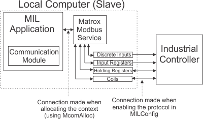
Once the instance of the Modbus communication protocol service has been enabled and configured using the MILConfig utility, you can allocate an Industrial Communication context for use with Modbus (McomAlloc() with M_COM_PROTOCOL_MODBUS) and use the McomWrite() and McomRead() functions to communicate with the Modbus controller.
Note that when you set the local computer as a slave device, McomWrite() actually writes to data tables in local memory the data to send to the Modbus controller on its next read cycle. Similarly, as a slave device, McomRead() actually reads the data tables in local memory for data received from the Modbus controller during its last write cycle. So, when you call McomWrite() / McomRead(), you must specify the data table to write/read.
The Modbus data tables are created in local memory when the Modbus service is enabled and configured to be in slave mode, using the MILConfig utility. The supported Modbus data tables are:
The coil and discrete input data tables support 1-bit data, while the input and holding register data tables support 16-bit data. The Modbus controller can write to either the coil or the holding register data tables, and can read from all the data tables. As such, you should expect new data received from the Modbus controller in the coil (M_COILS) and holding register (M_HOLDING_REGISTER) data tables. The local computer can write to any of the four data tables.
You can, for example, use McomRead() to receive a request from a Modbus controller to grab and analyze an image, and then return the analysis results, necessary for the automation process, back to the Modbus controller using McomWrite().
Data tables and their data fields
The MIL Industrial Communication module is very flexible, knowing that different applications need to send/receive different information to/from the Modbus controller. As such, it allows you to establish how to divide these data tables into different data fields (register fields). For example, you could organize your data as follows:
Note that this is only an example of how you can organize your data in the data tables. In addition, the software running on the Modbus controller (for example, a ladder logic software) must be aware of how the data is organized in the data tables.
Setting up the environment to use the local computer as a Modbus controller
When the local computer running MIL is using the Modbus protocol in a master configuration that uses TCP, you must configure the Interface item in the MILConfig utility to the network adapter that should be used to communicate. For better performance, you can also specify all the devices on the Modbus network in the MILConfig utility; in this case, for every slave device on the Modbus network, specify their Slave IDs and their IP addresses in the MILConfig utility.
When the local computer running MIL in a master configuration is not using the TCP protocol (that is, ASCII or RTU), you must select the serial port on the local computer from which to communicate (COM port), baud rate, parity (odd or even), stop bits (1 or 2), and the serial communication standard used (RS232 or RS485).

Reading and writing to slave devices as a Modbus controller
If the local computer is configured as a master device (controller), it can only write to a slave device's coils or holding registers. The local computer can read from any of the slave device's four data tables listed in the previous section. When reading or writing data to a slave device on a Modbus TCP network, you must specify both the device's slave ID and its IP address, along with the data table with which you intend to communicate. When reading or writing data to a slave device on a Modbus ASCII or RTU network, you must only specify the device's slave ID, along with the data table with which you intend to communicate.
The function codes that MIL uses to read and write to a slave device, when the local computer is a controller, are as follows:
|
Data table |
Read |
Write |
|
Coil |
01 |
15 |
|
Discrete Input |
02 |
N/A |
|
Input Register |
04 |
N/A |
|
Holding Register |
03 |
16 |