Deinterlacing
- See also

 Availability
 Previous
- Next

Interlacing artifacts result when analyzing an image grabbed with an interlaced camera. To enhance the quality of the image, you can apply a deinterlacing algorithm using MimDeinterlace().
To understand and differentiate between deinterlacing algorithms, knowledge of interlacing artifacts and the reason they occur in an image is important. When an interlaced camera acquires images, it captures two separate fields per frame. However, these fields are not acquired at the same moment in time. They are separated by 1/60 th of a second in NTSC or by 1/50 th of a second in PAL. In the event that an object was in motion when it was being acquired, its position would be slightly shifted from one field to the next, resulting in interlacing artifacts.
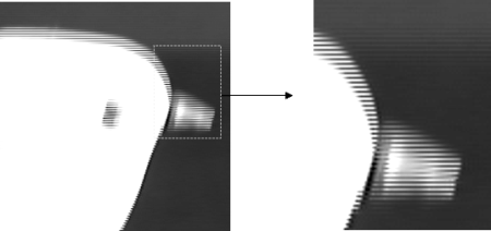
Taking a close look at the image, you can see a series of horizontal lines inside and around the edges of the bird. These lines are known as interlacing artifacts. The image is clearly formed by the superposition of two distinct fields, at two distinct moments in time.
MIL supports three different deinterlacing algorithms to reduce or remove interlacing artifacts: the discard, averaging, and bob algorithms. Note that interlacing artifacts are only present in objects in motion. MIL can apply these algorithms to all the pixels in an image or only to the pixels in the image that are part of objects in motion.
Discard algorithm on the entire image
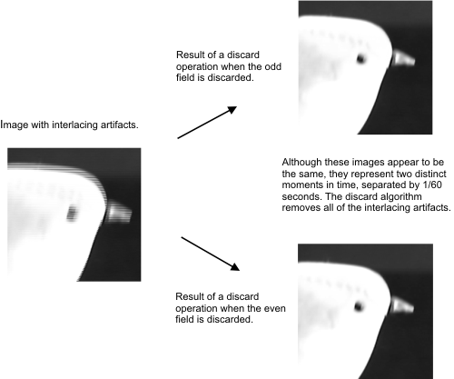
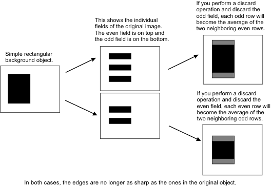
The discard algorithm, the simplest deinterlacing algorithm, removes one field from the image (the odd or even rows) and interpolates the remaining rows. For example, if you choose to discard the odd rows, the first odd row would be the average of the first and second even rows. This algorithm is advantageous because it removes all the interlacing artifacts and has a fast processing time. However, if the sequence of deinterlaced images is viewed as a video, the motion in the sequence will not be as fluid as the original sequence because each discarded field represents a unique moment in time. Also, the areas in the image that did not contain interlacing artifacts will lose sharpness in their edges.
The following example depicts the result of the discard algorithm on an image containing interlacing artifacts.
Averaging algorithm on the entire image
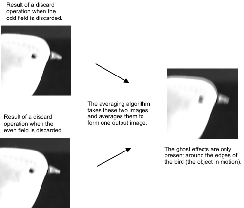
The averaging deinterlacing algorithm is equivalent to performing the discard algorithm once on the even field and once on the odd field and averaging the two resulting frames. In reality, MIL proceeds in a much more efficient way, making the processing speed of this function similar to the speed of the discard algorithm.
The interlacing artifacts are completely removed and this process preserves the fluidity of the video because complete fields are not discarded and therefore no individual moments in time are discarded. However, the images suffer from ghost effects (objects in motion appear in double) when looking at the stilled frames because two distinct moments in time are being merged together. These effects are barely noticeable when the images are viewed as a sequence. The loss of sharpness in background objects' edges also occurs when using this algorithm, but not as badly as with the discard algorithm.
The example below illustrates the ghost effects that arise from the averaging algorithm.
Bob algorithm on the entire image
The bob algorithm applies the discard algorithm twice, once to each field. The two frames that result each become an output frame. Therefore, for every input frame, there are two output frames. This algorithm completely removes the interlacing artifacts and the motion in the video is fluid. The processing speed of this algorithm is also fast, although not as fast as the discard or averaging algorithms. As for the image quality, the same loss of sharpness in static objects' edges is observed as with the discard algorithm. In addition, if the sequence of deinterlaced images is viewed in motion, the edges of static objects flutter occasionally.
The illustration below shows a sequence of frames, each representing the same background object. This is an example of the fluttering that can occur when viewing a sequence of deinterlacing images.

If the frames are displayed very quickly (1/30 th of a second on a progressive scan display), the top and bottom edges of the rectangle appear to be moving up and down, and it is this motion that we call fluttering.
Adaptive algorithms
MIL also supports an adaptive version of each algorithm: the adaptive discard, adaptive average, and adaptive bob algorithms. Since interlacing artifacts are caused by differences in successive frames and are only present in the areas of the image containing objects in motion, there is no need to apply the algorithms to all the pixels in the image; this actually results in a loss in the sharpness in the edges of static objects.
Therefore, prior to performing their respective deinterlacing operation, the adaptive algorithms first perform motion detection to determine the areas of the image depicting moving objects. To achieve this, each pixel in the frame to deinterlace is compared with the pixels at the same location in a group of neighboring frames. If the difference between the maximum and minimum pixel intensity is above a specified threshold value, the pixel in the frame to deinterlace is considered part of an object in motion. If the difference is below the threshold value, the pixel is considered part of a background object. After all the pixel locations have been checked, the deinterlacing algorithm is applied to the pixels in motion and the background pixels remain untouched.
Note that the adaptive algorithms are more effective in preserving the sharpness and detail in background objects, however they can fail to remove some subtle interlacing artifacts. In addition, they have a longer processing time than their non-adaptive counterparts.
If an adaptive algorithm is selected, each frame in the input sequence of images will undergo motion detection. Using MimControl(), you can set the number of neighboring frames used for motion detection (M_MOTION_DETECT_NUM_FRAMES), the location of the frame to be processed within this group of frames (M_MOTION_DETECT_REFERENCE_FRAME), and the threshold value used to differentiate between pixels of objects in motion and pixels of background objects (M_MOTION_DETECT_THRESHOLD). Note that in the motion detection process, MIL will automatically adjust the index of the reference frame within the group of neighboring frames for border frames, when necessary. For example, suppose you have specified a group of 3 frames to be used for motion detection, with the reference frame set to the center frame. In an input sequence of 5 images, the following image illustrates which frames are used for motion detection.
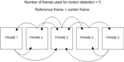
The frames at the extremities of the sequence cannot be the center frame in a group of 3 frames (because they do not have an adjacent frame on both their left and right side). Therefore, MIL takes this into account and changes the reference frame to avoid these problematic situations. In the example, the first frame has no frame on its left. The reference frame will be changed to the left frame (instead of the center frame) and the motion detection will be performed using the two frames on the right.
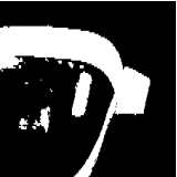
The image below is the result of the motion detection process. The white pixels represent pixels of objects in motion and the black pixels represent pixels of background objects. To generate images like this one, you use MimControl() with M_MOTION_DETECT_OUTPUT set to M_ENABLE. Note that in this case, the deinterlacing algorithm will not be performed.