Watershed transformations
- See also

 Availability
 Previous
- Next

-
Perform a distance transformation on the image. This will result in a grayscale image with a maximum in each object.
-
Perform a watershed transformation on the resulting image. Note that:
-
Catchment basins must be determined from the image's maxima rather than its minima since MimDistance() produces a maximum in each object.
-
The transform must show only watershed lines. To save time, you can prevent watershed lines from extending into the background. You can also specify that the watershed lines be straight. Note that these options are discussed in more detail later.
-
You must specify the minimum grayscale variation that is required to produce a new catchment basin (this is discussed in more detail later). In general, when separating touching objects in a binary image, a low value (2) is usually sufficient.
-
-
Perform an AND operation between the original image and the result of step 2, using MimArith().
-
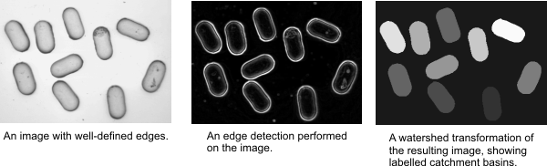
Perform an edge detection on the image.
-
Determine, through some analysis of the resulting image, the minimum grayscale variation that is required to produce a new catchment basin (this is discussed in the next section).
-
Perform a watershed transformation on the resulting image. You must specify that catchment basins be determined from the image's minima. In addition, the final image should only show labeled catchment basins.
-
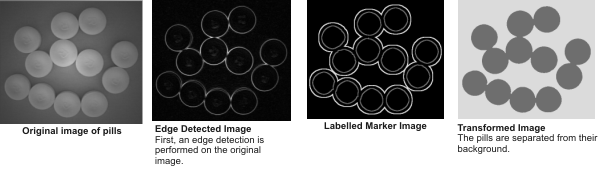
Perform an edge detection on the original image.
-
Create a marker image that is able to locate your objects in the image.
-
For this example, the labeled marker image is created from the edge detected image using a series of morphology, edge detection, and blob analysis operations.
-
In this example, the almost-white boundary surrounding all the rings is one marker. This marker serves to define the background and is placed in the corresponding area of the background of the original image.
-
All the rings in the marker image are considered to be one marker. This particular marker serves to identify the pills. These rings are smaller than the pills in the original image and are located in the corresponding areas of the pills.
-
-
Perform the watershed transformation on the edge detected image. You must specify that the catchment basins be determined from the image's minima. Remark how the resulting catchment basins have the same label value as the marker that generated them.
You can perform watershed transformations using MimWatershed(). A watershed transformation is generally used in conjunction with other processing operations to segment images, that is, to separate objects from their background and/or from each other.
To understand what a watershed transformation is, it is useful to think of an image as a topographic surface with hills and valleys. In other words, the value of each pixel represents a certain height, with the lowest pixel value (the darkest pixel) representing the point of lowest elevation and the highest pixel value (the brightest pixel) representing the point of highest elevation. A minimum in the image is defined as a pixel or a set of connected pixels that is lower in value (or elevation) than all its neighboring pixels. A maximum is a pixel or a set of connected pixels which is higher in value (elevation) than all its neighboring pixels. Pixels are connected if they are vertically, horizontally, or diagonally adjacent. A catchment basin refers to a minimum or maximum's zone of influence. For example, for a minimum, a catchment basin refers to the set of pixels from which, if a drop of water were to fall, it would eventually reach that minimum.
MimWatershed() labels an image's catchment basins and/or builds dividing lines between the catchment basins. These dividing lines are known as the watershed lines of the image. Note that catchment basins can be determined from the image's minima or its maxima.

Using watersheds to separate touching objects
You can use MimWatershed() in conjunction with MimDistance() and MimArith() to separate touching objects in a binary image.
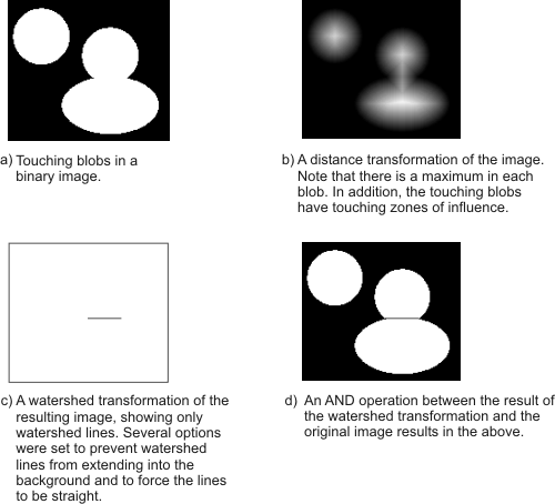
To summarize:
Using watersheds to separate objects from their background
MimWatershed() can be used in conjunction with other processing operations to separate objects from their background. For example, if the objects have well-defined edges, an edge detection will produce a maximum along the edges of each object. These maxima will define each object as a catchment basin since they produce a minimum in each object. A watershed transformation will then label the catchment basins, effectively segmenting the image.
To summarize:
Minimum grayscale variation of a catchment basin
A typical image contains a lot of unwanted extrema, often due to noise. If catchment basins were determined from each extremum, the transform would segment various noise areas, resulting in over-segmentation. To prevent over-segmentation while still separating objects from their background, you can specify the minimum grayscale variation of a catchment basin, using the MinVariation parameter of MimWatershed().
The minimum variation of a catchment basin can be more easily understood using the topographical surface analogy. When dealing with minima, the minimum grayscale variation can be thought of as the minimum depth of the valley required to produce a catchment basin. The reverse applies when dealing with maxima.
The following shows a line profile across an object in an image (after an edge detection is performed on the image). In this case, the maximum difference between gray levels in the background (as well as within the object) is about 10, and the minimum difference between the background and the edges is about 50. In this case, therefore, the MinVariation parameter should be set to a value somewhere between 10 and 50, for example, 30. Note that, if it is set above 50, the object will not be separated from the background since its extrema will not produce a new catchment basin.

The default value for the MinVariation parameter is 1, which means that each extremum produces a catchment basin.
Using marker images
If you are able to approximate the location of your objects in an image (either through some preprocessing or through some previous knowledge of the image), you might want catchment basins determined from a separate image (known as a marker image), instead of from the extrema in the source image. Marker images are useful in preventing over-segmentation since you control not only the location of the extrema but also the number of extrema.
If you use a marker image, you can set the MinVariation parameter to M_OFF or 0, since you mark off the extrema in a separate image.
There are two types of marker images: non-labeled and labeled.
Non-labeled marker images
In a non-labeled marker image, each group of touching pixels with the value zero in the marker image, known as a marker, starts a catchment basin in the corresponding area of the source image. Specifically, each marker in the marker image forces an extremum in the corresponding area of the source image. Pixels in the marker image are considered touching if they are vertically, horizontally, or diagonally adjacent, that is, if they are "8-connected".
Labeled marker images
In a labeled marker image, a marker is a set of pixels that do not have to necessarily touch and that have all the same label value (pixel intensity). Each marker starts a catchment basin in the corresponding area of the source image and each catchment basin of the destination image is assigned the label value of the marker that generated it. Note that, in a labeled marker image, a marker can touch other markers, allowing you to specify adjacent catchment basins. Valid marker label values are 1 to 2 n - 2 (where n is the marker image buffer depth). Pixels with the label value of 2 n - 1 are considered to be part of a "don't care" mask and are not processed, accelerating the watershed transformation. Finally, pixels with the label value of zero are interpreted as not being part of a marker. To use a labeled marker image, you must add M_LABELED_MARKER to the ControlFlag parameter.
The following is an example that performs a watershed transformation using a labeled marker image. It will separate the pills from the background.
To summarize:
Note that catchment basins can be determined from markers in the marker image as well as from extrema in the source image. In this case, supply a marker image to MimWatershed() and also specify the minimum grayscale variation in the source image required to produce a new catchment basin.
Style of the watershed lines
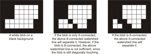
Watershed lines can be 8-connected or 4-connected (set the ControlFlag parameter of MimWatershed() to M_4_CONNECTED or M_8_CONNECTED). In addition, they can be traced exactly or forced to be straight (set ControlFlag to M_REGULAR or M_STRAIGHT_WATERSHED).
8-connected watershed lines consist of pixels that are horizontally, vertically, or diagonally touching. 4-connected watershed lines consist of pixels that are just horizontally and/or vertically touching. 8-connected watershed lines can separate 4-connected blobs, that is, blobs whose pixels can touch horizontally or vertically. 4-connected watershed lines are required to separate 8-connected blobs, that is, blobs whose pixels can touch horizontally, vertically, or diagonally.
MIL's Blob Analysis module allows you to define blobs as either 4- or 8-connected.
Note that 4-connected watershed lines can also separate 4-connected blobs, however they cause over-separation.
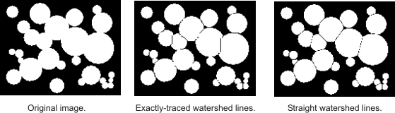
Exact versus straight
For visual purposes, watershed lines can be traced exactly or forced to be straight.
Skipping the last level
When you perform MimWatershed(), you can skip the last intensity level of the transformation (by setting the ControlFlag parameter to M_SKIP_LAST_LEVEL). In other words, you can prevent an extremum's zone of influence from extending beyond Lmax - 1 (for a minimum) or Lmin - 1 (for a maximum), where Lmax is the maximum gray level in the image and Lmin is the minimum gray level. In effect, this prevents the background in the image from being processed, resulting in quicker processing times.

This option should be used when separating touching objects since, in this case, watershed lines in the background are unnecessary.
Filling the source
When you perform MimWatershed(), you can fill the catchment basins of unwanted extrema in the source image by adding M_FILL_SOURCE to the ControlFlag parameter. M_FILL_SOURCE fills the catchment basins of the unwanted extrema until the local basins become plateaus. Any subsequent watershed transformation on the source image will no longer process the unwanted extrema because they are no longer extrema.
The following images illustrate how M_FILL_SOURCE transforms the source image:
