McalTransformCoordinate3dList
| MIL_ID CalibrationOrImageId, | //in |
| MIL_INT64 SrcCoordinateSystem, | //in |
| MIL_INT64 DstCoordinateSystem, | //in |
| MIL_INT NumPoints, | //in |
| const MIL_DOUBLE *SrcCoordXArrayPtr, | //in |
| const MIL_DOUBLE *SrcCoordYArrayPtr, | //in |
| const MIL_DOUBLE *SrcCoordZArrayPtr, | //in |
| MIL_DOUBLE *DstCoordXArrayPtr, | //out |
| MIL_DOUBLE *DstCoordYArrayPtr, | //out |
| MIL_DOUBLE *DstCoordZArrayPtr, | //out |
| MIL_INT64 ModeFlag | //in |
This function converts a list of coordinates from a source coordinate system to a destination coordinate system, where coordinates of unit direction vectors and of depth maps are also accepted as inputs for a coordinate system.
Using this function, you can convert between the following:
-
Pixel coordinate system and world coordinate system.
-
World coordinate system and any other world coordinate system.
-
Fully corrected depth maps and world coordinate system.
-
Pixel coordinate system and unit direction vectors in any world coordinate system.
Note that conversion between unit direction vectors and the pixel coordinate system is supported, but conversion of direction vectors to depth maps or world coordinate systems is not. Also, if you pass a corrected image to McalTransformCoordinate3dList(), and you specify that the source points are expressed in the pixel coordinate system (M_PIXEL_COORDINATE_SYSTEM), the function assumes that the source points are expressed in the corrected pixel coordinate system.
To convert a point from the pixel coordinate system to its corresponding point in the specified world coordinate system, this function creates a line (simulating a light ray) from the effective pinhole of the camera through the specified point in the image plane, and then to the specified relative coordinate system (DstCoordinateSystem). Since all points along a given light ray project onto the same point in the image plane, every point along the ray is theoretically a solution. Therefore, to produce a unique solution, the point of intersection between the line and the XY-plane (Z=0) of the relative coordinate system is transformed to the specified world coordinate system. Then, the corresponding world point is returned. Alternatively, McalTransformCoordinate3dList() can return the X, Y, and Z-components of the unit direction vector corresponding to the direction of the calculated light ray as it intersects the source point (using M_UNIT_DIRECTION_VECTOR).
If the image plane is not parallel to the XY-plane (Z=0) of the relative coordinate system, due to the camera setup or a displacement of the relative coordinate system, not every point in the image plane will have a valid real-world equivalent. Three types of intersections can occur when transforming from the image plane to the world plane. If the specified point in the image plane corresponds to a point in front of the camera in the relative coordinate system, its corresponding position in the destination world coordinate system is returned. However, if the line traced through the specified point in the image plane does not intersect the XY-plane of the relative coordinate system, M_INVALID_POINT is returned. If the projected line's intersection with the XY-plane of the relative coordinate system is behind the camera, the mathematically computed value of this point of intersection is returned. Because this point of intersection is located behind the camera, its location in the relative coordinate system is considered as incorrect.
However, using M_NO_POINTS_BEHIND_CAMERA with McalTransformCoordinate3dList() returns M_INVALID_POINT if the returned point is behind the camera.
To convert a point specified in a world coordinate system to its corresponding point in the pixel coordinate system, the function transforms the specified point to the relative coordinate system and a line is formed (simulating a light ray) from the point in the XY-plane (Z=0) of the relative coordinate system to the effective pinhole of the camera. The function then returns the point of intersection of this line with the image plane. If the point given is behind the camera, the function will return the mathematically computed value. However, using M_NO_POINTS_BEHIND_CAMERA with McalTransformCoordinate3dList() will return M_INVALID_POINT instead of the mathematically computed value.
This function also supports the conversion of coordinates from a depth map to a specified world coordinate system and vice versa. To convert from a depth map to a world coordinate system, you must provide the depth map's X and Y coordinates and, optionally, the intensity value of the pixel. You can choose to omit the intensity value, in which case the function will obtain the value from the specified location in the depth map. If you choose to omit the intensity values, set SrcCoordZArrayPtr to M_NULL. The intensity value of the depth map point is linearly mapped to a corresponding Z-coordinate for the world coordinate system. Note, source pixel coordinates that are outside the depth map image will generate M_INVALID_POINT.
If the intensity of a depth map pixel is equal to the buffer's maximum intensity value, it is interpreted as missing data and cannot be converted. M_INVALID_POINT will be returned. Note, that this applies whether you choose to omit the intensity values or not.
To convert a point from a specified world coordinate system to a depth map, you must provide the X-, Y-, and Z-coordinates of the point. The function converts the X-, Y-, and Z-coordinates of the world coordinate system to X, Y and intensity values, respectively. The Z-coordinate of the world coordinate system is linearly mapped to a corresponding intensity value where the maximum Z-coordinate in the list is given the highest possible depth value and the minimum Z-coordinate is give the lowest possible depth value.
Specifies the identifier of a camera calibration context, calibrated image, or corrected image. When an identifier of an image buffer is specified, the transformation uses the calibration information associated with this image.
If you are transforming coordinates obtained from a calibrated image, you can pass either its identifier or the identifier of its calibration context. However, if the coordinates are obtained from a child buffer of a calibrated image, you must only pass the identifier of the child buffer.
Specifies the coordinate system of the source coordinates. This parameter must be set to one of the following values:
 For specifying the type of the source
coordinate system
For specifying the type of the source
coordinate system |
|||||||||||||||||||||||||||||||||||||||
  Value Value |
Description
|
||||||||||||||||||||||||||||||||||||||
|
M_ABSOLUTE_COORDINATE_SYSTEM |
Specifies an implicit and fixed coordinate system from which all other world coordinate systems are defined. |
||||||||||||||||||||||||||||||||||||||
|
M_CAMERA_COORDINATE_SYSTEM |
Specifies the coordinate system whose origin corresponds to the effective pinhole of the camera and whose Z-axis points in the direction that the camera is facing. |
||||||||||||||||||||||||||||||||||||||
| M_PIXEL_COORDINATE_SYSTEM |
Specifies the pixel coordinate system of the image passed to CalibrationOrImageId (corrected or uncorrected); if a calibration context is passed instead, the pixel coordinate system is of any image that has the same pixel-to-world mapping as the specified calibration context. (more details...) |
||||||||||||||||||||||||||||||||||||||
|
M_RELATIVE_COORDINATE_SYSTEM |
Specifies the relative coordinate system. (more details...) |
||||||||||||||||||||||||||||||||||||||
|
M_ROBOT_BASE_COORDINATE_SYSTEM |
Specifies the coordinate system whose origin is positioned at the base of the robot holding the camera. (more details...) |
||||||||||||||||||||||||||||||||||||||
| M_TOOL_COORDINATE_SYSTEM |
Specifies the coordinate system used to position the camera. (more details...) |
||||||||||||||||||||||||||||||||||||||
Specifies the coordinate system in which to return the coordinates. This parameter must be set to one of the following values:
|
For specifying the type of the
destination coordinate system |
|||||||||||||||||||||||||||||||||||||||
| Value |
Description
|
||||||||||||||||||||||||||||||||||||||
|
M_ABSOLUTE_COORDINATE_SYSTEM |
Specifies an implicit and unmovable coordinate system from which all other world coordinate systems are defined. |
||||||||||||||||||||||||||||||||||||||
|
M_CAMERA_COORDINATE_SYSTEM |
Specifies the coordinate system whose origin corresponds to the effective pinhole of the camera and whose Z-axis points in the direction that the camera is facing. |
||||||||||||||||||||||||||||||||||||||
| M_PIXEL_COORDINATE_SYSTEM |
Specifies the pixel coordinate system of the image passed to CalibrationOrImageId (only if uncorrected); if a calibration context is passed instead, the pixel coordinate system is of any image that has the same pixel-to-world mapping as the specified calibration context. (more details...) |
||||||||||||||||||||||||||||||||||||||
|
M_RELATIVE_COORDINATE_SYSTEM |
Specifies the relative coordinate system. (more details...) |
||||||||||||||||||||||||||||||||||||||
|
M_ROBOT_BASE_COORDINATE_SYSTEM |
Specifies the coordinate system whose origin is positioned at the base of the robot holding the camera. (more details...) |
||||||||||||||||||||||||||||||||||||||
| M_TOOL_COORDINATE_SYSTEM |
Specifies the coordinate system used to position the camera. (more details...) |
||||||||||||||||||||||||||||||||||||||
Specifies the address of the array containing the X-coordinates of the source points. These coordinates must be expressed in the source coordinate system.
Specifies the address of the array containing the Y-coordinates of the source points. These coordinates must be expressed in the source coordinate system.
Specifies the address of the array containing the Z-coordinates of the source points. These coordinates must be expressed in the source coordinate system.
This parameter must be set to M_NULL if the source coordinate system is set to M_PIXEL_COORDINATE_SYSTEM. If the source coordinate system is a world coordinate system and the calibration information associated to CalibrationOrImageId is using a 2D calibration mode, this parameter must either be set to M_NULL or all the Z-coordinates must be set to 0.
Specifies the address of the array in which to return the X-coordinates of the resulting points or the X-components of the calculated unit direction vectors, depending on the transformation mode (ModeFlag) . These coordinates are expressed in the destination coordinate system.
If one of the source points cannot be converted, the entry in the destination array corresponding to such point is set to M_INVALID_POINT.
Specifies the address of the array in which to return the Y-coordinates of the resulting points or the Y-components of the calculated unit direction vectors, depending on the transformation mode (ModeFlag) . These coordinates are expressed in the destination coordinate system.
If one of the source points cannot be converted, the entry in the destination array corresponding to such point is set to M_INVALID_POINT.
Specifies the address of the array in which to return the Z-coordinates of the resulting points or the Z-components of the calculated unit direction vectors, depending on the transformation mode (ModeFlag) . These coordinates are expressed in the destination coordinate system.
If one of the source points cannot be converted, the entry in the destination array corresponding to such point is set to M_INVALID_POINT.
This parameter must be set to M_NULL if the destination coordinate system is set to M_PIXEL_COORDINATE_SYSTEM.
Specifies the mode of transformation and how to deal with invalid points.
You can set the ModeFlag parameter to one of the following values to specify the mode of transformation.
|
For specifying the mode of
transformation |
|||||||||||||||||||||||||||||||||||||||
| Value |
Description
|
||||||||||||||||||||||||||||||||||||||
|
M_DEFAULT |
Specifies the default mode of transformation. (more details...) |
||||||||||||||||||||||||||||||||||||||
| M_DEPTH_MAP + |
Specifies that the source or destination coordinate systems are interpreted as depth map coordinates. (more details...) |
||||||||||||||||||||||||||||||||||||||
| M_UNIT_DIRECTION_VECTOR + |
Specifies that points expressed in a world coordinate system, whether source or destination coordinates, are interpreted as unit direction vectors along the simulated light ray (instead of 3D points). The unit direction vectors are going from the effective pinhole of the camera to the pixel coordinate system. This transformation mode is only available when converting points in the pixel coordinate system to unit direction vectors in any world coordinate system, and vice-versa. When SrcCoordinateSystem is set to M_PIXEL_COORDINATE_SYSTEM, unit direction vectors are generated for each point specified in the image plane. When DstCoordinateSystem is set to M_PIXEL_COORDINATE_SYSTEM, points in the image plane corresponding to the unit direction vectors specified are returned. 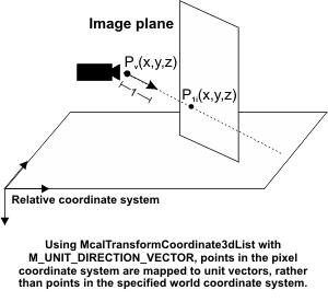
Specifies that points expressed in a world coordinate system, whether source or destination coordinates, are interpreted as unit direction vectors along the simulated light ray (instead of 3D points). (more details...) |
||||||||||||||||||||||||||||||||||||||
You can use one or more of the following values in combination with each other or with the above-mentioned values, to specify when to return M_INVALID_POINT.
|
For specifying when to return
M_INVALID_POINT |
|||||||||||||||||||||||||||||||||||||||
| Value |
Description
|
||||||||||||||||||||||||||||||||||||||
| M_NO_EXTRAPOLATED_POINTS |
Specifies that if a pixel involved in the transformation is not inside the calibrated region, M_INVALID_POINT will be returned, instead of a coordinate resulting from the extrapolation. (more details...) |
||||||||||||||||||||||||||||||||||||||
| M_NO_POINTS_BEHIND_CAMERA |
Specifies that M_INVALID_POINT is returned when a computed point is mathematically valid but physically impossible (behind the camera). (more details...) |
||||||||||||||||||||||||||||||||||||||
| Header | Include mil.h. |
| Library | Use mil.lib; milcal.lib. |
| DLL | Requires mil.dll; milcal.dll. |