Moving the relative coordinate system
There are five ways to fixture the relative coordinate system to an object:
-
Move it to the position and angle of a specified occurrence of a MIL Pattern Matching or Model Finder model.
-
Move it to the position and angle of a specified Metrology reference frame feature.
-
Move it to a position and angle that are with respect to a relative coordinate system.
-
Move it to a position and angle that are with respect to the absolute coordinate system.
-
Move it to a position and angle using one of the above techniques, and then copy its position and angle to other images that require the same relative coordinate system displacement.
Moving using a model
The easiest way to move the relative coordinate system for fixturing is to use a MIL Pattern Matching or Model Finder model that is at a fixed positional and angular offset from the object to analyze or process. In this case, search for the model. Then, to move the relative coordinate system to the reference location of a found occurrence, call McalFixture() with M_MOVE_RELATIVE, the Model Finder/Pattern Matching result buffer, and the index of the occurrence.
For example, to move the relative coordinate system of an image to the reference location of the first occurrence of a pattern matching model:
/* Move the relative coordinate system of ImageId, with no offset,
   at the location of occurrence 0 of the pattern matching model,
   (location is contained in the pattern matching result PatResultId). */
McalFixture(ImageId, M_NULL, M_MOVE_RELATIVE, M_RESULT_PAT, PatResultId,
            0, /* Occurrence index = 0. */
            M_DEFAULT, M_DEFAULT, M_DEFAULT);
You should ensure that the Pattern Matching or Model Finder model used to establish the location has good, unique features so that there is no ambiguity over where to move the relative coordinate system.
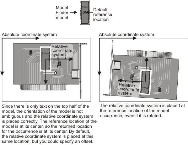
By default, when using this technique, the relative coordinate system is placed at the reference location of the specified model occurrence. You can, however, set the relative coordinate system at an offset from this location. See the Fixturing offset section later in this chapter.
For more information about defining a Pattern Matching model, see Chapter 6: Pattern matching. For more information about defining a Model Finder model, see Chapter 7: Geometric Model Finder.
Moving using a metrology reference frame
You can specify the new location for the relative coordinate system using the position and angle of a Metrology reference frame. To do so, call McalFixture() with M_MOVE_RELATIVE, the identifier of a Metrology result buffer, and the index of the reference frame feature to use. MIL will move the relative coordinate system to the location, offset, and angle specified by the constructed Metrology reference frame.
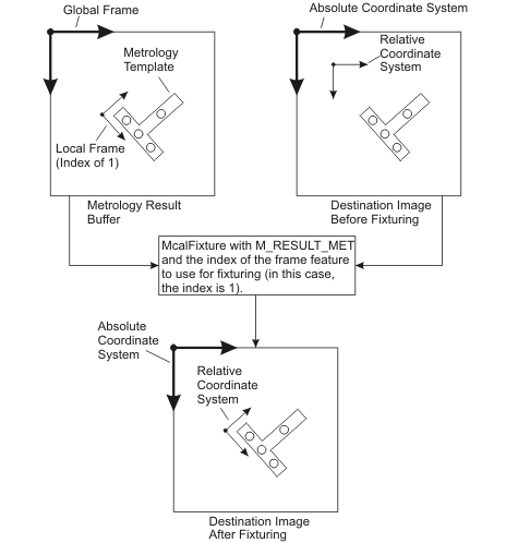
The constructed frames used in metrology are not valid in any other module, and so moving the relative coordinate system to the location specified by the constructed frame could be useful to, for example, process the same image using a different module after having processed it with Metrology.
/* Move the relative coordinate system of ImageId, with no offset,
   at the location of the local frame 1 of the metrology context,
   (location is contained in the metrology result MetResultId). */
McalFixture(ImageId, M_NULL, M_MOVE_RELATIVE, M_RESULT_MET, MetResultId,
            1, /* Local frame index = 1. */
            M_DEFAULT, M_DEFAULT, M_DEFAULT);
By default, when using this technique, the relative coordinate system is placed at the reference location of the specified Metrology global or local frame result. You can, however, set the relative coordinate system at an offset from this location. See the Fixturing offset section later in this chapter.
Moving using a position and angle expressed in a specified relative coordinate system
You can have MIL establish the new location for the relative coordinate system based on an explicitly specified position and angle that are expressed in a specified relative coordinate system. In this case, the position and angle would correspond to a calculated reference location for the object to analyze or process.
To move the relative coordinate system using this technique, call McalFixture() with all of the following:
-
The position and angle expressed in a relative coordinate system.
-
The calibrated image/calibration context with the relative coordinate system of the position and angle. Typically, this is the current relative coordinate system of the target image.
Internally, McalFixture() converts the specified position and angle to be with respect to the absolute coordinate system. It then uses the converted position and angle to place the new relative coordinate system.
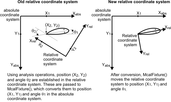
For the example above, you would call McalFixture() with the position (X2, Y2) and angle Theta2, which are expressed in the current relative coordinate system. McalFixture() will then internally calculate and place the relative coordinate system at the position (X1, Y1) and angle Theta1 in the absolute coordinate system.
/* Move the relative coordinate system of ImageId, with no offset,
   at the position (X2, Y2) and angle Theta2.
   This point and this angle are expressed in the relative coordinate
   system of ImageId (before the move).
   After the move, the relative coordinate system will be placed at position (X1, Y1)
   and angle Theta1. */
McalFixture(ImageId, M_NULL, M_MOVE_RELATIVE, M_POINT_AND_ANGLE,
            M_DEFAULT, /* CS for (X2, Y2) and Theta2: M_DEFAULT means use ImageId. */
            X2, Y2, Theta2, M_DEFAULT);
By default, the relative coordinate system is placed at the calculated position and angle. You can, however, set the relative coordinate system at an offset from the calculated position and angle. See the Fixturing offset section later in this chapter.
Moving using a position and angle that are with respect to the absolute coordinate system
If you know the position and angle for the new relative coordinate system with respect to the absolute coordinate system, you can set the new relative coordinate system directly, using McalRelativeOrigin() or McalSetCoordinateSystem().
For example, if in the previous example, you knew the position (X1, Y1) and angle Theta1 in the absolute coordinate system, you could call McalRelativeOrigin() as follows:
/* Move the relative coordinate system of ImageId, with no offset,
   at the position (X1, Y1) and angle Theta1.
   This point and this angle are expressed in the absolute coordinate system. */
McalRelativeOrigin(ImageId, X1, Y1, 0.0, Theta1, M_DEFAULT);
Copying the new relative coordinate system to other images
When working with multiple images of the same scene taken from different view points, you might want to move the relative coordinate system in one image, and then copy the position and angle of the new relative coordinate system to the other images. To perform the copy, iteratively call McalFixture() with all of the following:
-
Call McalFixture() with M_MOVE_RELATIVE as the Operation and M_SAME_AS_SOURCE as the LocationType.
-
Specify the source calibration context to be copied in CalOrLocSourceId.
-
Specify the destination of the copy operation in DstCalibratedMilObjectId.
This operation does not copy the absolute coordinate system information. It assumes that the absolute coordinate systems of the different images are the same, although the mapping between the world and pixel coordinate systems might be different.
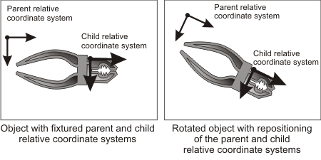
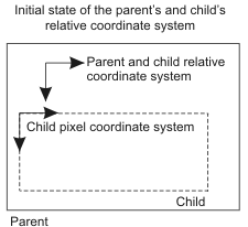
Displacing the relative coordinate system of parent and child buffers
Since a child buffer receives a copy of the calibration information stored in the parent, it initially has a copy of the parent's relative coordinate system that takes into account the different origin in the pixel coordinate system.
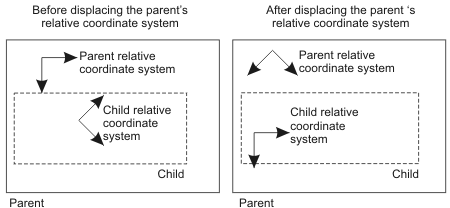
You can displace the relative coordinate system of the child; this does not affect the relative coordinate system of the parent. This allows you to analyze different aspects of an image with respect to different relative coordinate systems, while preserving the location of the relative coordinate system of the parent buffer.
However, if you change the relative coordinate system of the parent, the child's relative coordinate system will also be displaced. There exists a rigid link between the position and orientation of the parent and child buffers' relative coordinate systems. Consequently, if you have multiple child buffers, their relative coordinate system will be changed to maintain the same pose that was previously established with respect to the parent coordinate system.
If you need more than one relative coordinate system for an image, you can allocate child buffers that have the same size as the parent; as expected, each will have its own copy of the relative coordinate system. This allows you to not only have multiple relative coordinate systems but also perform operations with respect to different reference points. If you have an image that contains a complex object with multiple features that you want to analyze, you can fixture the relative coordinate system of the parent to the object, and then fixture each child buffer's relative coordinate system to one of the object's features. This ensures that when you locate the object in general and move the parents buffer's relative coordinate system, the relative coordinate systems of the child buffers are relocated to the correct position, due to the rigid link between the two coordinate systems. This allows the complex features of the object to be easily analyzed when the parent's relative coordinate system is fixtured to a new instance of the object.