McalSetCoordinateSystem
| MIL_ID CalibratedMilObjectId, | //in |
| MIL_INT64 TargetCoordinateSystem, | //in |
| MIL_INT64 ReferenceCoordinateSystem, | //in |
| MIL_INT64 TransformType, | //in |
| MIL_ID MatrixId, | //in |
| MIL_DOUBLE Param1, | //in |
| MIL_DOUBLE Param2, | //in |
| MIL_DOUBLE Param3, | //in |
| MIL_DOUBLE Param4 | //in |
This function moves a specified (target) coordinate system in relation to a specified (reference) coordinate system. For example, you can move the relative coordinate system by (0, 6, 0) in the absolute coordinate system. This will displace the origin of the relative coordinate system by 6 units along the Y-axis of the absolute coordinate system. You can call this function with either a single calibration context, calibrated image, or 3D reconstruction result buffer of type M_POINT_CLOUD_CONTAINER. Note that to return the position and orientation of one coordinate system as a transformation of another coordinate system, you can use McalGetCoordinateSystem().
If you are moving the relative coordinate system of an image that has been corrected, the XY-plane of the relative coordinate system should not be moved in the Z-direction and should not be rotated around its X or Y-axis. In other words, the relative coordinate system of a corrected image can only be translated along its X or Y-axis or rotated around its Z-axis. Moving the relative coordinate system of an image is useful for analyzing an object using a temporary local coordinate system. You can also use McalFixture() to move the relative coordinate system with respect to a result. If you move the relative coordinate system, results returned in world units from other modules are returned with respect to the relative coordinate system's new position, and settings which accept input in world units will accept that input with respect to the relative coordinate system's new position.
This function can only be used with 3D-based calibration contexts (M_TSAI_BASED or M_3D_ROBOTICS).
If you transform the camera or tool coordinate system, MIL assumes that the camera has been moved in your camera setup, so it adjusts the calibration mapping between the absolute coordinate system and the pixel coordinate system.
This function can also be used to transform the relative coordinate system of a 3D reconstruction result buffer of type M_POINT_CLOUD_CONTAINER, which M3dmapGetResult() and M3dmapGet() use to express world coordinates and which defines the projection orientation for M3dmapExtract(). To perform the transformation of a coordinate system in a result buffer, TargetCoordinateSystem must be set to M_RELATIVE_COORDINATE_SYSTEM and ReferenceCoordinateSystem must be set to M_RELATIVE_COORDINATE_SYSTEM or M_ABSOLUTE_COORDINATE_SYSTEM.
Note that all angles should be given in degrees. However, unlike most other MIL functions (including McalRelativeOrigin()), angles are interpreted using the right-hand grip rule around the axis of rotation; if you wrap your right hand around the axis of rotation, pointing your thumb in the positive direction of the axis, your fingers wrap in the direction of rotation. For example, a positive rotation around the Z-axis corresponds to a rotation that turns the positive X-axis toward the positive Y-axis.
You can specify whether the transformation of the target coordinate system is applied from the current position (M_COMPOSE_WITH_CURRENT) of the target coordinate system or from the origin of the reference coordinate system (M_ASSIGN).
Note that you cannot move the pixel coordinate system nor the absolute coordinate system.
If you adjust the coordinate system of a calibrated image associated with an M_VECTOR_AND_RASTER ROI, the raster information will be discarded, causing the ROI to become an M_VECTOR ROI. See MbufSetRegion() for more information.
Specifies the identifier of a calibration context, 3D reconstruction result buffer of type M_POINT_CLOUD_CONTAINER, or a calibrated image.
Specifies the coordinate system on which to apply the transformation. This parameter can be set to one of the following:
If CalibratedMilObjectId is set to a 3D reconstruction result buffer (must be of type M_POINT_CLOUD_CONTAINER) or a calibrated image, TargetCoordinateSystem must be set to M_RELATIVE_COORDINATE_SYSTEM.
 For specifying the target coordinate
system
For specifying the target coordinate
system |
|||||||||||||||||||||||||||||||||||||||
  Value Value |
Description
|
||||||||||||||||||||||||||||||||||||||
|
M_CAMERA_COORDINATE_SYSTEM |
Specifies to apply the transformation to the camera coordinate system. (more details...) |
||||||||||||||||||||||||||||||||||||||
|
M_RELATIVE_COORDINATE_SYSTEM |
Specifies to apply the transformation to the relative coordinate system. (more details...) |
||||||||||||||||||||||||||||||||||||||
|
M_ROBOT_BASE_COORDINATE_SYSTEM |
Specifies to apply the transformation to the robot-base coordinate system. (more details...) |
||||||||||||||||||||||||||||||||||||||
| M_TOOL_COORDINATE_SYSTEM |
Specifies to apply the transformation to the tool coordinate system. (more details...) |
||||||||||||||||||||||||||||||||||||||
Specifies the reference coordinate system. The reference coordinate system must be defined before calling this function. This parameter can be set to one of the following values:
If your CalibratedMilObjectId is a 3D reconstruction result buffer (must be of type M_POINT_CLOUD_CONTAINER), ReferenceCoordinateSystem must be set to M_RELATIVE_COORDINATE_SYSTEM or M_ABSOLUTE_COORDINATE_SYSTEM.
|
For specifying the reference coordinate
system |
|||||||||||||||||||||||||||||||||||||||
| Value |
Description
|
||||||||||||||||||||||||||||||||||||||
|
M_DEFAULT |
Same as M_ABSOLUTE_COORDINATE_SYSTEM. |
||||||||||||||||||||||||||||||||||||||
|
M_ABSOLUTE_COORDINATE_SYSTEM |
Specifies to use the absolute coordinate system as a reference coordinate system for the transformation. (more details...) |
||||||||||||||||||||||||||||||||||||||
|
M_CAMERA_COORDINATE_SYSTEM |
Specifies to use the camera coordinate system as a reference coordinate system for the transformation. (more details...) |
||||||||||||||||||||||||||||||||||||||
|
M_RELATIVE_COORDINATE_SYSTEM |
Specifies to use the relative coordinate system as a reference coordinate system for the transformation. (more details...) |
||||||||||||||||||||||||||||||||||||||
|
M_ROBOT_BASE_COORDINATE_SYSTEM |
Specifies to use the robot base coordinate system as a reference coordinate system for the transformation. (more details...) |
||||||||||||||||||||||||||||||||||||||
| M_TOOL_COORDINATE_SYSTEM |
Specifies to use the tool coordinate system as a reference coordinate system for the transformation. (more details...) |
||||||||||||||||||||||||||||||||||||||
Specifies the type of transformation to apply to the target coordinate system.
See the Parameter associations section for possible values that can be specified.
Specifies the identifier of a MIL array buffer which contains the transformation matrix to use. The expected transformation matrix is dependent on the type of transformation selected.
The MIL array buffer must be a 32-bit floating-point buffer, allocated using MbufAlloc2d() with M_ARRAY. The required buffer size is dependent on the type of transformation selected.
Set this parameter to M_NULL if not used.
See the Parameter associations section for possible values that can be specified.
Specifies an attribute of the transformation. Its definition is dependent on the type of transformation selected.
Set this parameter to M_DEFAULT if not used.
See the Parameter associations section for possible values that can be specified.
Specifies an attribute of the transformation. Its definition is dependent on the type of transformation selected.
Set this parameter to M_DEFAULT if not used.
See the Parameter associations section for possible values that can be specified.
Specifies an attribute of the transformation. Its definition is dependent on the type of transformation selected.
Set this parameter to M_DEFAULT if not used.
See the Parameter associations section for possible values that can be specified.
Specifies an attribute of the transformation. Its definition is dependent on the type of transformation selected.
Set this parameter to M_DEFAULT if not used.
See the Parameter associations section for possible values that can be specified.
The table below lists possible values for the TransformType, MatrixId, Param1, Param2, Param3, and Param4 parameters.
Note that if Param1, Param2, Param3, or Param4 are not required by the transformation, they should be set to M_DEFAULT.
|
For specifying the type of
transformation |
|||||||||||||||||||||||||||||||||||||||
| TransformType |
Description
|
||||||||||||||||||||||||||||||||||||||
| MatrixId | |||||||||||||||||||||||||||||||||||||||
| Param1 | |||||||||||||||||||||||||||||||||||||||
| Param2 | |||||||||||||||||||||||||||||||||||||||
| Param3 | |||||||||||||||||||||||||||||||||||||||
| Param4 | |||||||||||||||||||||||||||||||||||||||
|
M_HOMOGENEOUS_MATRIX + |
Specifies to apply a translation, a rotation, or both to the target coordinate system. (more details...) |
||||||||||||||||||||||||||||||||||||||
| MatrixId |
Specifies the matrix representation of the transformation. (more details...) |
||||||||||||||||||||||||||||||||||||||
|
M_IDENTITY + |
Specifies to apply the identity transformation to the target coordinate system. (more details...) |
||||||||||||||||||||||||||||||||||||||
| MatrixId |
This parameter must be set to M_NULL. |
||||||||||||||||||||||||||||||||||||||
|
M_ROTATION_AXIS_ANGLE + |
Specifies to apply a rotation operation described by an axis and angle of rotation. The axis of rotation is defined by the origin of the reference coordinate system and one other point. The angle of rotation is measured in the counter-clockwise direction around the axis of rotation. 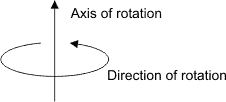
You must specify a combination value from the following table: Specifies to apply a rotation operation described by an axis and angle of rotation. (more details...) |
||||||||||||||||||||||||||||||||||||||
| MatrixId |
This parameter must be set to M_NULL. |
||||||||||||||||||||||||||||||||||||||
| Param1 |
Specifies the X-coordinate of the point which defines the axis of rotation. |
||||||||||||||||||||||||||||||||||||||
| Param2 |
Specifies the Y-coordinate of the point which defines the axis of rotation. |
||||||||||||||||||||||||||||||||||||||
| Param3 |
Specifies the Z-coordinate of the point which defines the axis of rotation. |
||||||||||||||||||||||||||||||||||||||
| Param4 |
Specifies the angle of the rotation, in degrees, around the axis of rotation. (more details...) |
||||||||||||||||||||||||||||||||||||||
|
M_ROTATION_MATRIX + |
Specifies to apply a rotation operation that is described by a 3x3 rotation matrix. (more details...) |
||||||||||||||||||||||||||||||||||||||
| MatrixId |
Specifies the matrix representation of the rotation. (more details...) |
||||||||||||||||||||||||||||||||||||||
|
M_ROTATION_QUATERNION + |
Specifies to apply a rotation operation that is described by a rotation quaternion. (more details...) |
||||||||||||||||||||||||||||||||||||||
| MatrixId |
This parameter must be set to M_NULL. |
||||||||||||||||||||||||||||||||||||||
| Param1 |
Specifies the scalar component of the quaternion. |
||||||||||||||||||||||||||||||||||||||
| Param2 |
Specifies the X-component of the quaternion. |
||||||||||||||||||||||||||||||||||||||
| Param3 |
Specifies the Y-component of the quaternion. |
||||||||||||||||||||||||||||||||||||||
| Param4 |
Specifies the Z-component of the quaternion. |
||||||||||||||||||||||||||||||||||||||
|
M_ROTATION_X + |
Specifies to apply a rotation operation that is described by a rotation around the X-axis. (more details...) |
||||||||||||||||||||||||||||||||||||||
| MatrixId |
This parameter must be set to M_NULL. |
||||||||||||||||||||||||||||||||||||||
| Param1 |
Specifies the X-axis rotation, in degrees. (more details...) |
||||||||||||||||||||||||||||||||||||||
|
M_ROTATION_XYZ + |
Specifies to apply a rotation operation that is described by three distinct rotations about the axes of the reference coordinate system in the following order: a rotation about the X-axis, a rotation about the Y-axis, and a rotation about Z-axis rotation. (more details...) |
||||||||||||||||||||||||||||||||||||||
| MatrixId |
This parameter must be set to M_NULL. |
||||||||||||||||||||||||||||||||||||||
| Param1 |
Specifies the X-axis rotation, in degrees. (more details...) |
||||||||||||||||||||||||||||||||||||||
| Param2 |
Specifies the Y-axis rotation, in degrees. (more details...) |
||||||||||||||||||||||||||||||||||||||
| Param3 |
Specifies the Z-axis rotation, in degrees. (more details...) |
||||||||||||||||||||||||||||||||||||||
|
M_ROTATION_XZY + |
Specifies to apply a rotation operation that is described by three distinct rotations about the axes of the reference coordinate system in the following order: a rotation about the X-axis, a rotation about the Z-axis, and a rotation about the Y-axis rotation. (more details...) |
||||||||||||||||||||||||||||||||||||||
| MatrixId |
This parameter must be set to M_NULL. |
||||||||||||||||||||||||||||||||||||||
| Param1 |
Specifies the X-axis rotation, in degrees. (more details...) |
||||||||||||||||||||||||||||||||||||||
| Param2 |
Specifies the Z-axis rotation, in degrees. (more details...) |
||||||||||||||||||||||||||||||||||||||
| Param3 |
Specifies the Y-axis rotation, in degrees. (more details...) |
||||||||||||||||||||||||||||||||||||||
|
M_ROTATION_Y + |
Specifies to apply a rotation operation that is described by a rotation about the Y-axis. (more details...) |
||||||||||||||||||||||||||||||||||||||
| MatrixId |
This parameter must be set to M_NULL. |
||||||||||||||||||||||||||||||||||||||
| Param1 |
Specifies the Y-axis rotation, in degrees. (more details...) |
||||||||||||||||||||||||||||||||||||||
|
M_ROTATION_YXZ + |
Specifies to apply a rotation operation that is described by three distinct rotations about the axes of the reference coordinate system in the following order: a rotation about the Y-axis, a rotation about the X-axis, and a rotation about Z-axis rotation. (more details...) |
||||||||||||||||||||||||||||||||||||||
| MatrixId |
This parameter must be set to M_NULL. |
||||||||||||||||||||||||||||||||||||||
| Param1 |
Specifies the Y-axis rotation, in degrees. (more details...) |
||||||||||||||||||||||||||||||||||||||
| Param2 |
Specifies the X-axis rotation, in degrees. (more details...) |
||||||||||||||||||||||||||||||||||||||
| Param3 |
Specifies the Z-axis rotation, in degrees. (more details...) |
||||||||||||||||||||||||||||||||||||||
|
M_ROTATION_YZX + |
Specifies to apply a rotation operation that is described by three distinct rotations about the axes of the reference coordinate system in the following order: a rotation about the Y-axis, a rotation about the Z-axis, and a rotation about the X-axis rotation. (more details...) |
||||||||||||||||||||||||||||||||||||||
| MatrixId |
This parameter must be set to M_NULL. |
||||||||||||||||||||||||||||||||||||||
| Param1 |
Specifies the Y-axis rotation, in degrees. (more details...) |
||||||||||||||||||||||||||||||||||||||
| Param2 |
Specifies the Z-axis rotation, in degrees. (more details...) |
||||||||||||||||||||||||||||||||||||||
| Param3 |
Specifies the X-axis rotation, in degrees. (more details...) |
||||||||||||||||||||||||||||||||||||||
|
M_ROTATION_Z + |
Specifies to apply a rotation operation that is described by a rotation about the Z-axis. (more details...) |
||||||||||||||||||||||||||||||||||||||
| MatrixId |
This parameter must be set to M_NULL. |
||||||||||||||||||||||||||||||||||||||
| Param1 |
Specifies the Z-axis rotation, in degrees. (more details...) |
||||||||||||||||||||||||||||||||||||||
|
M_ROTATION_ZXY + |
Specifies to apply a rotation operation that is described by three distinct rotations about the axes of the reference coordinate system in the following order: a rotation about the Z-axis, a rotation about the X-axis, and a rotation about the Y-axis rotation. (more details...) |
||||||||||||||||||||||||||||||||||||||
| MatrixId |
This parameter must be set to M_NULL. |
||||||||||||||||||||||||||||||||||||||
| Param1 |
Specifies the Z-axis rotation, in degrees. (more details...) |
||||||||||||||||||||||||||||||||||||||
| Param2 |
Specifies the X-axis rotation, in degrees. (more details...) |
||||||||||||||||||||||||||||||||||||||
| Param3 |
Specifies the Y-axis rotation, in degrees. (more details...) |
||||||||||||||||||||||||||||||||||||||
|
M_ROTATION_ZYX + |
Specifies to apply a rotation operation that is described by three distinct rotations about the axes of the reference coordinate system in the following order: a rotation about the Z-axis, a rotation about the Y-axis, and a rotation about the X-axis rotation. (more details...) |
||||||||||||||||||||||||||||||||||||||
| MatrixId |
This parameter must be set to M_NULL. |
||||||||||||||||||||||||||||||||||||||
| Param1 |
Specifies the Z-axis rotation, in degrees. (more details...) |
||||||||||||||||||||||||||||||||||||||
| Param2 |
Specifies the Y-axis rotation, in degrees. (more details...) |
||||||||||||||||||||||||||||||||||||||
| Param3 |
Specifies the X-axis rotation, in degrees. (more details...) |
||||||||||||||||||||||||||||||||||||||
|
M_TRANSLATION + |
Specifies to apply a translation operation along each of the reference coordinate system's axes. (more details...) |
||||||||||||||||||||||||||||||||||||||
| MatrixId |
This parameter must be set to M_NULL. |
||||||||||||||||||||||||||||||||||||||
| Param1 |
Specifies the displacement along the X-axis of the reference coordinate system. |
||||||||||||||||||||||||||||||||||||||
| Param2 |
Specifies the displacement along the Y-axis of the reference coordinate system. |
||||||||||||||||||||||||||||||||||||||
| Param3 |
Specifies the displacement along the Z-axis of the reference coordinate system. |
||||||||||||||||||||||||||||||||||||||
You must add one of the following values to the above-mentioned values to specify how to apply the transformation.
|
For specifying how to apply the
transformation |
|||||||||||||||||||||||||||||||||||||||
| Combination value |
Description
|
||||||||||||||||||||||||||||||||||||||
|
M_ASSIGN |
Specifies to assign the specified transformation to the target coordinate system from the origin and orientation of the reference coordinate system. (more details...) |
||||||||||||||||||||||||||||||||||||||
| M_COMPOSE_WITH_CURRENT |
Specifies to compose the specified transformation with the current position and orientation in the reference coordinate system. (more details...) |
||||||||||||||||||||||||||||||||||||||
| Header | Include mil.h. |
| Library | Use mil.lib; milcal.lib. |
| DLL | Requires mil.dll; milcal.dll. |