Manipulating the view
- See also

 Availability
 Previous
- Next

-
M_VIEWPOINT: The position from which the view is looking.
-
M_INTEREST_POINT: The position the view is looking at. This point is always at the center of the window.
-
M_UP_VECTOR: The vector which defines what is "up" for the view. This vector normalized and perpendicular to the view's line of sight. If you specify an up-vector that is not perpendicular to the line of sight, an appropriate, valid vector will automatically be calculated.
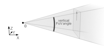
These settings define the position and rotation of your view, as shown in the following image:

-
M_FOV_HORIZONTAL_ANGLE / M_FOV_VERTICAL_ANGLE: The angles which determine how wide the view is. Increasing one of these angles has an effect similar to using a wider angle lens on a camera. To prevent distortion, MIL automatically updates these angles to have the same ratio as the horizontal and vertical resolution of the window. For example, if the user increases the horizontal window size, the horizontal FoV will automatically be increased proportionally.
MIL 3D graphics are 3D shapes that can be viewed from any angle (this includes 3D graphics associated with depth map image buffers and 3D-displayable containers). A 3D graphics list is a collection of these 3D shapes. When a 3D display is shown, a specific view of the contents of the 3D graphics list is rendered on the screen. You can manipulate the view of a 3D display, either interactively using the keyboard and mouse or within your application using M3ddispSetView() and M3ddispControl().
You can change the keyboard control bindings, or disable the ability to manipulate the view interactively, using M3ddispControl().
Fundamental view settings
The view is defined by 4 fundamental settings, set using M3ddispControl() and M3ddispSetView(). All other operations that you can perform using M3ddispSetView() are alternate methods for changing the fundamental settings. For example, the M_ROLL operation modifies the view's M_UP_VECTOR control type setting.
Fundamental settings that control the view position and rotation
The following fundamental view settings are available with M3ddispSetView().
Alternative view settings
You can use operations in M3ddispSetView() to define the viewpoint, interest point, and up-vector based on alternative models. You can use any combination of these models to manipulate the view in your 3D display. For example, you can set the initial view using M_VIEW_BOX, and then use M_AZIMUTH to rotate the viewpoint around the interest point.
If one of the operations described below could achieve the specified result by moving either the viewpoint or interest point (for example, M_VIEW_ORIENTATION), the viewpoint will be moved unless M_MOVE_INTEREST_POINT is used.
View orientation and distance
You can define the view by specifying the orientation of the viewpoint relative to the interest point using the M_VIEW_ORIENTATION operation. The vector that you specify is normalized and multiplied by M_DISTANCE, and the view is changed so that the viewpoint is offset from the interest point by the resulting vector. Similarly, you can use M_DISTANCE to change the distance between the viewpoint and interest point without changing the view orientation.
Instead of specifying your own orientation vector, you can specify a preset orientation (such as M_FRONT_VIEW).
Azimuth, elevation, roll, and distance
You can define the view in a spherical model that is always aligned with the working coordinate system of the 3D display using operatons such as M_AZIM_ELEV_ROLL. Using this model, the viewpoint is always a fixed distance (specified using M_DISTANCE) from the interest point. M_AZIMUTH is the rotation (between 0 and 360 degrees) around the interest point in the plane that intersects the interest point and is parallel to the XY-plane of the working coordinate system of the 3D display. M_ELEVATION is the vertical rotation (between -90 and 90 degrees) around the interest point. M_ROLL is the rotation (between 0 and 360 degrees) of the view around pole described by the viewpoint and interest point. The up-vector is determined based on the elevation and roll.
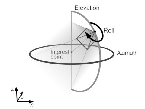
Note that, for elevation settings that are close to 90 or -90, MIL cannot deterministically calculate the azimuth and roll of the view. In this case, inquiring the azimuth or roll will return practically random values. Similarly, setting the azimuth or roll with the combination value M_COMPOSE_WITH_CURRENT will not produce reliable results.
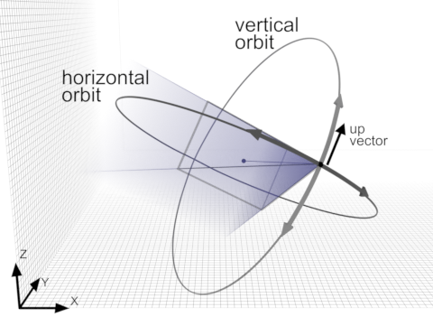
Orbit, up-vector, and distance
You can define the view in a spherical model that is relative to the current position and orientation of the view using M_ORBIT_HORIZONTAL and M_ORBIT_VERTICAL. Using this model, the viewpoint is always a fixed distance (specified using M_DISTANCE) from the interest point. When you use M_ORBIT_VERTICAL, the viewpoint orbits around the interest point in the direction of the up-vector by the specified number of degrees. When you use M_ORBIT_HORIZONTAL, the viewpoint orbits around the interest point in the direction perpendicular the up-vector by the specified number of degrees.
Unlike azimuth and elevation, vertical and horizontal orbit are always specified relative to the current position and orientation of the view. For example, repeatedly using M3ddispSetView() with M_ORBIT_HORIZONTAL and the value 90 will repeatedly orbit the viewpoint around the interest point, in 90 degree increments.
The following animation shows the effect of setting the horizontal and vertical orbit of the view, in relation to the up-vector and the working coordinate system of the 3D display.

View box
You can define the view by specifying to show everything within a specified area using the M_VIEW_BOX operation and specifying a 3D box geometry object (previously allocated using M3dgeoAlloc() and defined using M3dgeoBox()). This operation keeps the viewpoint and interest point in the same orientation relative to each other (M_VIEW_ORIENTATION does not change), but moves the viewpoint and interest point such that the interest point is at the center of the box geometry object, and the viewpoint is the correct distance away to show the entire region defined by the box.
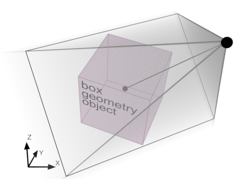
Instead of the identifier of a 3D box geometry object, you can specify M_WHOLE_SCENE to perform the same operation on a hypothetical box that encompasses everything in the 3D display's 3D graphics list.
View matrix
You can define the view by specifying a transformation matrix using M_VIEW_MATRIX. If the transformation matrix is the identity matrix, the viewpoint will be at (0,0,1), with the interest point at the origin (0,0,0) and an up-vector of (0,1,0). This can also be thought of as a direct top-down view, with the up-vector aligned with the Y-axis.
You can store the current transformation matrix of the view using M3ddispCopy(), and then restore the same view later using M3ddispSetView() with M_VIEW_MATRIX.
Other 3D display controls
You can define other aspects of the 3D display, including the background, rotation indicator, and whether the view rotates automatically.
Changing the background
By default the background of a 3D display is a vertical gradient with colors suitable for viewing most objects. Optionally, you can change the background settings using M3ddispControl().
You can change the background mode with M_BACKGROUND_MODE. You can specify to show the background as a solid color with the M_SINGLE_COLOR setting, or to show a background image using the M_BACKGROUND_IMAGE setting.
You can change the colors of the background with the M_BACKGROUND_COLOR and M_BACKGROUND_COLOR_GRADIENT settings. When the background is a gradient, M_BACKGROUND_COLOR is the color at the top of the 3D display and M_BACKGROUND_COLOR_GRADIENT is the color at the bottom of the 3D display.
To set the background image, copy an 8-bit unsigned image buffer to the 3D display using M3ddispCopy() with M_BACKGROUND_IMAGE. If the background image has a different aspect ratio than the window, the image will be stretched in the 3D display. You can determine the size and number of bands of the current background image buffer using M3ddispInquire() with M_BACKGROUND_IMAGE_SIZE_....
Rotation indicator
You can enable a visual indicator of the orientation of the view, using M3ddispControl() with M_ROTATION_INDICATOR. The rotation indicator is always positioned at the interest point and is always rotated so that it is aligned with the working coordinate system of the 3D display.
Auto-rotation
You can have the view automatically rotate around a specified axis, using M3ddispControl() with M_AUTO_ROTATE. This is useful for showing a whole 3D scene without user input.
By default, the view auto-rotates around the first 3D graphic added to the internal 3D graphics list of the 3D display. You can change the auto-rotation axis using M3ddispCopy() with M_ROTATION_AXIS and the MIL identifier of a 3D line geometry object.
Note that both the viewpoint and the interest point move during auto-rotation. Some users might be disoriented by the view rotating around an axis that does not intersect the interest point, especially when the rotation indicator is enabled.