M3ddispSetView
- See also

 Availability
 Function map
- Examples
 M3ddispSelect
- M3ddispSelectWindow

3dmodelheightdefect.cpp
3dplanarity.cpp
3dplanefit.cpp
3dprofilemetrology.cpp
blisterpackinspection.cpp
bottlecapinspection.cpp
c3ddisplaymanager.cpp
cameraonrobotarmcalibration.cpp
cookiedetection.cpp
m3ddisp.cpp
m3ddisp.cs
m3ddisp.vb
m3dgra.cpp
m3dgra.cs
m3dgra.vb
m3dmap.cpp
m3dmap.cs
m3dmap.vb
m3dreg.cpp
m3dreg.cs
m3dreg.vb
pointcloudprojection.cpp
simple3dbinpicking.cpp
simple3dstitching.cpp
sphereinspection.cpp
stereocalibration.cpp
studinspection.cpp
tirestringread.cpp
| Table: | For setting the view |
| + combination: | Specifies whether the motion is absolute or relative. |
| + combination: | Specifies whether the interest point should move |
| MIL_ID Disp3dId, | //in |
| MIL_INT64 Mode, | //in |
| MIL_DOUBLE Param1, | //in |
| MIL_DOUBLE Param2, | //in |
| MIL_DOUBLE Param3, | //in |
| MIL_INT64 ControlFlag | //in |
This function changes the position and orientation of the view of the specified 3D display.
Note that, by default, you can also change the position of orientation of the view interactively using the keyboard and mouse. You can enable or disable the keyboard and mouse controls using M3ddispControl() with M_KEYBOARD_USE and M_MOUSE_USE.
This function changes the view of the 3D display by modifying the viewpoint, interest point, and/or up vector, as shown in the image below:
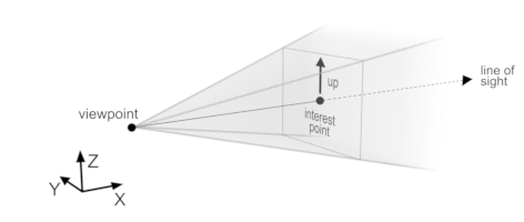
You can set the position of the viewpoint using M_VIEWPOINT, the position of the interest point using M_INTEREST_POINT and the direction of the up vector using M_UP_VECTOR. All other modes are alternatives to adjusting these aspects of the view directly. For example, setting the M_ROLL of the view is an alternate method to change the M_UP_VECTOR setting.
Most modes are specified in absolute terms (for example, using M_AZIMUTH with the value 90 sets the azimuth to 90, regardless of the current value). In some cases, you can instead specify to apply the operation relative to the current state of the view using M_COMPOSE_WITH_CURRENT. For example, if you use M_AZIMUTH with M_COMPOSE_WITH_CURRENT and the value 90, and the current azimuth is 30, the new azimuth is 120.
Modes that can be performed by moving either the viewpoint or the interest point will always move the viewpoint, unless you use the combination value M_MOVE_INTEREST_POINT. For example, if you use M_AZIMUTH with the value 45, by default the viewpoint is moved to the position that is rotated 45 degrees around the interest point (relative to the plane that intersects the interest point and is parallel to the ZY-plane), effectively circling the view around the interest point. If you specify M_MOVE_INTEREST_POINT, instead the interest point is moved to the position in which the viewpoint is rotated 45 degrees around the interest point, effectively panning the view. Both modes result in the same orientation (the viewpoint is rotated 45 degrees around the interest point); however, in the first case the viewpoint has a new position, and in the second case the interest point has a new position.
Optionally, you can specify not to refresh the rendered image shown in the 3D display by setting the ControlFlag parameter to M_NO_REFRESH. This is useful for making several consecutive changes to the view while only displaying the final result. The view begins refreshing again the next time you use M3ddispSetView() without specifying M_NO_REFRESH.
Specifies the mode used for setting the view.
See the Parameter associations section for possible values that can be specified.
Specifies the first parameter used to set the view.
See the Parameter associations section for possible values that can be specified.
Specifies the second parameter used to set the view.
Set this parameter to M_DEFAULT if not used.
See the Parameter associations section for possible values that can be specified.
Specifies the third parameter used to set the view.
Set this parameter to M_DEFAULT if not used.
See the Parameter associations section for possible values that can be specified.
Specifies if the 3D display should be refreshed.
|
For specifying if the display should be
updated |
|||||||||||||||||||||||||||||||||||||||
| Description | |||||||||||||||||||||||||||||||||||||||
|
Specifies to refresh the 3D display immediately after the operation is complete. |
|||||||||||||||||||||||||||||||||||||||
|
Specifies not to refresh the 3D display immediately after the operation is complete. This can be used to call the function multiple times before the 3D display is refreshed. (summarize)Specifies not to refresh the 3D display immediately after the operation is complete. (more details...) |
|||||||||||||||||||||||||||||||||||||||
The table below lists possible values for the Mode, Param1, Param2, and Param3 parameters.
|
For setting the view
|
|||||||||||||||||||||||||||||||||||||||
| Description | |||||||||||||||||||||||||||||||||||||||
| Param1 | |||||||||||||||||||||||||||||||||||||||
| Param2 | |||||||||||||||||||||||||||||||||||||||
| Param3 | |||||||||||||||||||||||||||||||||||||||
|
Same as M_AUTO. (summarize)Same as M_AUTO. (more details...) |
|||||||||||||||||||||||||||||||||||||||
|
Sets the viewpoint and interest point position so that everything in the scene is within the view. (summarize)Sets the viewpoint and interest point position so that everything in the scene is within the view. (more details...) |
|||||||||||||||||||||||||||||||||||||||
|
Specifies one of the following. (summarize)Specifies one of the following. (more details...) |
|||||||||||||||||||||||||||||||||||||||
|
Specifies that the orientation of the view is preserved. The viewpoint and interest point are moved so that the entire contents of the 3D graphics list are centered and visible in the view. (summarize)Specifies that the orientation of the view is preserved. (more details...) |
|||||||||||||||||||||||||||||||||||||||
|
Specifies to use a view that is an interpolation between bottom, front, and left views. |
|||||||||||||||||||||||||||||||||||||||
|
Specifies to set the orientation of the view so that the viewpoint is directly below the interest point (parallel to the Z-axis of the working coordinate system of the 3D display). |
|||||||||||||||||||||||||||||||||||||||
|
Specifies to set the orientation of the view so that the viewpoint is directly in front of the interest point (parallel to the Y-axis of the working coordinate system of the 3D display). |
|||||||||||||||||||||||||||||||||||||||
|
Specifies to set the orientation of the view so that the viewpoint is directly to the left of the interest point (parallel to the X-axis of the working coordinate system of the 3D display). |
|||||||||||||||||||||||||||||||||||||||
|
Specifies to set the orientation of the view so that the viewpoint is directly behind the interest point (parallel to the Y-axis of the working coordinate system of the 3D display). |
|||||||||||||||||||||||||||||||||||||||
|
Specifies to set the orientation of the view so that the viewpoint is directly to the right of the interest point (parallel to the X-axis of the working coordinate system of the 3D display). |
|||||||||||||||||||||||||||||||||||||||
|
Specifies to use a view that is an interpolation between top, front, and left views. |
|||||||||||||||||||||||||||||||||||||||
|
Specifies to set the orientation of the view so that the viewpoint is directly above the interest point (parallel to the Z-axis of the working coordinate system of the 3D display). |
|||||||||||||||||||||||||||||||||||||||
|
Sets the azimuth and elevation of the viewpoint relative to the interest point, and the roll of the view. These are the viewpoint position and up vector, described in a spherical coordinate system (additionally described by M_DISTANCE). Azimuth is the angle of the viewpoint relative to the interest point on the XY-plane. An azimuth of 0 corresponds to a view where the viewpoint and interest point are parallel to the X-axis on the XY-plane, with the viewpoint on the positive side. Increasing values for the azimuth correspond to rotating the view counter-clockwise around the interest point. Elevation is the angle of the viewpoint relative to the interest point on the XZ-plane. An elevation of 0 corresponds to a view where the viewpoint and interest point are parallel to the X-axis on the XZ-plane, with the viewpoint on the positive side. Increasing values for the elevation correspond to rotating the view counter-clockwise around the interest point in the XZ-plane. Roll is the angle that describes how much the view is rotated to the right. A roll of 0 corresponds to a view for which up is positive on the Z-axis. 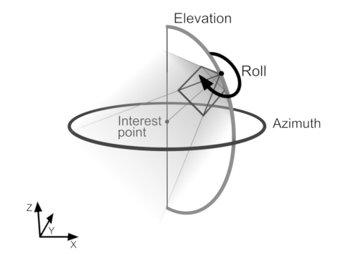
Sets the azimuth and elevation of the viewpoint relative to the interest point, and the roll of the view. (more details...) |
|||||||||||||||||||||||||||||||||||||||
|
Specifies the azimuth of the viewpoint relative to the interest point, in degrees. |
|||||||||||||||||||||||||||||||||||||||
|
Specifies the elevation of the viewpoint relative to the interest point, in degrees. |
|||||||||||||||||||||||||||||||||||||||
|
Specifies the roll of the view, in degrees. |
|||||||||||||||||||||||||||||||||||||||
|
Sets the azimuth of the view. (summarize)Sets the azimuth of the view. (more details...) |
|||||||||||||||||||||||||||||||||||||||
|
Specifies the azimuth of the view relative to the interest point. |
|||||||||||||||||||||||||||||||||||||||
|
Sets the distance between the viewpoint and the interest point. (summarize)Sets the distance between the viewpoint and the interest point. (more details...) |
|||||||||||||||||||||||||||||||||||||||
|
Specifies the distance between the viewpoint and the interest point. |
|||||||||||||||||||||||||||||||||||||||
|
Sets the elevation of the view relative to the interest point. (summarize)Sets the elevation of the view relative to the interest point. (more details...) |
|||||||||||||||||||||||||||||||||||||||
|
Specifies the elevation of the view relative to the interest point. |
|||||||||||||||||||||||||||||||||||||||
|
Sets the view to a position and orientation that is flipped around the interest point in the specified axis. (summarize)Sets the view to a position and orientation that is flipped around the interest point in the specified axis. (more details...) |
|||||||||||||||||||||||||||||||||||||||
|
Specifies one of the following. (summarize)Specifies one of the following. (more details...) |
|||||||||||||||||||||||||||||||||||||||
|
Specifies to flip the viewpoint around the interest point in the specified axis. |
|||||||||||||||||||||||||||||||||||||||
|
Specifies to flip the viewpoint around the interest point in the specified axis. |
|||||||||||||||||||||||||||||||||||||||
|
Specifies to flip the viewpoint around the interest point in the specified axis. |
|||||||||||||||||||||||||||||||||||||||
|
Sets the position of the interest point. (summarize)Sets the position of the interest point. (more details...) |
|||||||||||||||||||||||||||||||||||||||
|
Specifies the X-coordinate of the position of the interest point. |
|||||||||||||||||||||||||||||||||||||||
|
Specifies the Y-coordinate of the position of the interest point. |
|||||||||||||||||||||||||||||||||||||||
|
Specifies the Z-coordinate of the position of the interest point. |
|||||||||||||||||||||||||||||||||||||||
|
Sets the angle of the viewpoint's horizontal orbit around the interest point. This angle is used relative to the M_UP_VECTOR of the view. For more information, see the Orbit, up-vector, and distance subsection of the Manipulating the view section of Chapter 37: 3D Display and graphics. 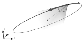
Note that orbit is always specified relative to the current position of the view. For example, repeatedly using this function with M_ORBIT_HORIZONTAL and the value 90 will repeatedly orbit the viewpoint horizontally around the interest point, in 90 degree increments. (summarize)Sets the angle of the viewpoint's horizontal orbit around the interest point. (more details...) |
|||||||||||||||||||||||||||||||||||||||
|
Specifies the angle of the viewpoint's horizontal orbit around the interest point. |
|||||||||||||||||||||||||||||||||||||||
|
Sets the angle of the viewpoint's vertical orbit around the interest point. This angle is used relative to the M_UP_VECTOR of the view. For more information, see the Orbit, up-vector, and distance subsection of the Manipulating the view section of Chapter 37: 3D Display and graphics. 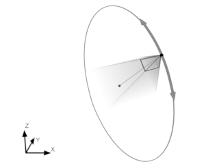
Note that orbit is always specified relative to the current position of the view. For example, repeatedly using this function with M_ORBIT_VERTICAL and the value 90 will repeatedly orbit the viewpoint vertically around the interest point, in 90 degree increments. (summarize)Sets the angle of the viewpoint's vertical orbit around the interest point. (more details...) |
|||||||||||||||||||||||||||||||||||||||
|
Specifies the angle of the viewpoint's vertical orbit around the interest point. |
|||||||||||||||||||||||||||||||||||||||
|
Sets the roll of the view. This is an angle which defines what direction the top of the view will be pointing, with 0 degrees specifying that the view will be perfectly level. As this value increases, the view rolls to the right. (summarize)Sets the roll of the view. (more details...) |
|||||||||||||||||||||||||||||||||||||||
|
Specifies the roll of the view, in degrees. |
|||||||||||||||||||||||||||||||||||||||
|
Applies a translation to the viewpoint and interest point without altering their relative position and orientation. (summarize)Applies a translation to the viewpoint and interest point without altering their relative position and orientation. (more details...) |
|||||||||||||||||||||||||||||||||||||||
|
Specifies the translation along the X-axis to apply to the positions of the viewpoint and interest point. |
|||||||||||||||||||||||||||||||||||||||
|
Specifies the translation along the Y-axis to apply to the positions of the viewpoint and interest point. |
|||||||||||||||||||||||||||||||||||||||
|
Specifies the translation along the Z-axis to apply to the positions of the viewpoint and interest point. |
|||||||||||||||||||||||||||||||||||||||
|
Sets the vector which defines what direction the top of the view is pointing. Note that this setting is normalized and adjusted to a unit vector that is orthogonal to the current orientation of the view. If you use M3ddispGetView() with M_UP_VECTOR after setting the up vector, the returned value will therefore typically be different from the vector you specified. (summarize)Sets the vector which defines what direction the top of the view is pointing. (more details...) |
|||||||||||||||||||||||||||||||||||||||
|
Specifies the X-component of the up vector of the view. |
|||||||||||||||||||||||||||||||||||||||
|
Specifies the Y-component of the up vector of the view. |
|||||||||||||||||||||||||||||||||||||||
|
Specifies the Z-component of the up vector of the view. |
|||||||||||||||||||||||||||||||||||||||
|
Sets the viewpoint and interest point (without altering the orientation) such that the interest point is at the center of the box and the entire region defined by the box is within view. 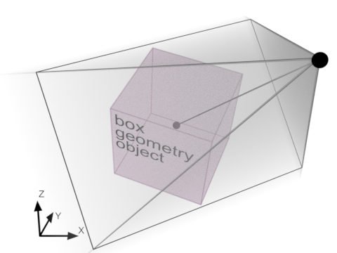
Sets the viewpoint and interest point (without altering the orientation) such that the interest point is at the center of the box and the entire region defined by the box is within view. (more details...) |
|||||||||||||||||||||||||||||||||||||||
|
Specifies one of the following. (summarize)Specifies one of the following. (more details...) |
|||||||||||||||||||||||||||||||||||||||
|
Specifies to set the viewpoint and interest point so that everything in the scene is within the view. |
|||||||||||||||||||||||||||||||||||||||
|
Specifies the identifier of the 3D box geometry object used to set the 3D display's view. The 3D box geometry object must have been previously allocated using M3dgeoAlloc() with M_GEOMETRY, and must have been successfully defined. (summarize)Specifies the identifier of the 3D box geometry object used to set the 3D display's view. (more details...) |
|||||||||||||||||||||||||||||||||||||||
|
Specifies one of the following. (summarize)Specifies one of the following. (more details...) |
|||||||||||||||||||||||||||||||||||||||
|
Specifies the default value; the default value is 1. |
|||||||||||||||||||||||||||||||||||||||
|
Specifies the scale factor. The position for the viewpoint is calculated as though the box is scaled by this factor. (summarize)Specifies the scale factor. (more details...) |
|||||||||||||||||||||||||||||||||||||||
|
Sets the view to match a transformation matrix. If the transformation matrix is the identity matrix, the viewpoint will be at (0,0,1), with the interest point at the origin (0,0,0) and an up-vector of (0,1,0). This can also be thought of as a direct top-down view, with the up-vector aligned with the Y-axis. You must specify the MIL identifier of a similarity transformation matrix. You can determine whether a transformation matrix is a similarity transformation matrix using M3dgeoInquire() with M_SIMILARITY. (summarize)Sets the view to match a transformation matrix. (more details...) |
|||||||||||||||||||||||||||||||||||||||
|
Specifies the following. (summarize)Specifies the following. (more details...) |
|||||||||||||||||||||||||||||||||||||||
|
Specifies the MIL identifier of a similarity transformation matrix (previously allocated using M3dgeoAlloc() with M_TRANSFORMATION_MATRIX). |
|||||||||||||||||||||||||||||||||||||||
|
Sets the direction in which the view is looking. This moves the viewpoint (or interest point if combined with M_MOVE_INTEREST_POINT) so that line of sight matches a given orientation, specified using either a predefined orientation or a vector that defines the direction from the viewpoint to the interest point. (summarize)Sets the direction in which the view is looking. (more details...) |
|||||||||||||||||||||||||||||||||||||||
|
Specifies one of the following. (summarize)Specifies one of the following. (more details...) |
|||||||||||||||||||||||||||||||||||||||
|
Specifies to use a view that is an interpolation between bottom, front, and left views. |
|||||||||||||||||||||||||||||||||||||||
|
Specifies to set the orientation of the view so that the viewpoint is directly below the interest point (parallel to the Z-axis of the working coordinate system of the 3D display). |
|||||||||||||||||||||||||||||||||||||||
|
Specifies to set the orientation of the view so that the viewpoint is directly in front of the interest point (parallel to the Y-axis of the working coordinate system of the 3D display). |
|||||||||||||||||||||||||||||||||||||||
|
Specifies to set the orientation of the view so that the viewpoint is directly to the left of the interest point (parallel to the X-axis of the working coordinate system of the 3D display). |
|||||||||||||||||||||||||||||||||||||||
|
Specifies to set the orientation of the view so that the viewpoint is directly behind the interest point (parallel to the Y-axis of the working coordinate system of the 3D display). |
|||||||||||||||||||||||||||||||||||||||
|
Specifies to set the orientation of the view so that the viewpoint is directly to the right of the interest point (parallel to the X-axis of the working coordinate system of the 3D display). |
|||||||||||||||||||||||||||||||||||||||
|
Specifies to use a view that is an interpolation between top, front, and left views. |
|||||||||||||||||||||||||||||||||||||||
|
Specifies to set the orientation of the view so that the viewpoint is directly above the interest point (parallel to the Z-axis of the working coordinate system of the 3D display). |
|||||||||||||||||||||||||||||||||||||||
|
Specifies the X-component of the vector that defines the orientation of the view. |
|||||||||||||||||||||||||||||||||||||||
|
Specifies the Y-component of the vector that defines the orientation of the view. |
|||||||||||||||||||||||||||||||||||||||
|
Specifies the Z-component of the vector that defines the orientation of the view. |
|||||||||||||||||||||||||||||||||||||||
|
Sets the position of the view. (summarize)Sets the position of the view. (more details...) |
|||||||||||||||||||||||||||||||||||||||
|
Specifies the X-coordinate of the position of the view. |
|||||||||||||||||||||||||||||||||||||||
|
Specifies the Y-coordinate of the position of the view. |
|||||||||||||||||||||||||||||||||||||||
|
Specifies the Z-coordinate of the position of the view. |
|||||||||||||||||||||||||||||||||||||||
|
Zooms the view in or out by a factor. This is equivalent to dividing M_DISTANCE by the specified factor. (summarize)Zooms the view in or out by a factor. (more details...) |
|||||||||||||||||||||||||||||||||||||||
|
Specifies the factor by which to zoom the view. This must be set to a value greater than 0.0. (summarize)Specifies the factor by which to zoom the view. (more details...) |
|||||||||||||||||||||||||||||||||||||||
You can add the following value to the above-mentioned values to specify that the viewpoint is moved relative to the current position and orientation of the viewpoint..
|
Specifies whether the motion is absolute or
relative.
|
|||||||||||||||||||||||||||||||||||||||
| Description | |||||||||||||||||||||||||||||||||||||||
|
Specifies that the view is altered relative to the current position and orientation of the view. |
|||||||||||||||||||||||||||||||||||||||
You can add the following value to the above-mentioned values to specify that the interest point is moved instead of the viewpoint..
|
Specifies whether the interest point should
move
|
|||||||||||||||||||||||||||||||||||||||
| Description | |||||||||||||||||||||||||||||||||||||||
|
Specifies that the interest point is moved instead of the viewpoint. |
|||||||||||||||||||||||||||||||||||||||
| Header | Include mil.h. |
| Library | Use mil.lib; mil3d.lib. |
| DLL | Requires mil.dll; mil3d.dll. |