How to fixture in 3D
- See also

 Availability
 Previous
- Next

-
Allocate a transformation matrix object using M3dgeoAlloc().
-
Generate the required transformation coefficients by calling M3dgeoMatrixSetTransform() with the transformation that you want to perform (for example, M_TRANSLATION), or by calling M3dgeoMatrixSetWithAxes() with the origin and axes that define your new working coordinate system. Alternatively, you can copy a resulting matrix from another MIL 3D module (for example, the 3D Metrology or 3D Registration module) into the transformation matrix object.
-
Apply the transformation matrix to the 3D points using M3dimMatrixTransform(). Typically, you store the resulting transformed points in a different container if your source point cloud has multiple regions that need to be analyzed.
-
Fixturing to a known position.
-
Fixturing to a reference object.
-
Fixturing to a plane.
-
Play speed: Start position: Looping: - 1 of 16
-
Isolate the region in the object's point cloud using M3dimCrop().
-
Fit a plane to this region, using M3dmetFit().
-
Apply the resulting transformation matrix to the points, using M3dimMatrixTransform().
-
Play speed: Start position: Looping: - 1 of 11
You might want to apply the same measurement or inspection process to every instance of an object that could appear any number of times at any location or orientation in your 3D scene. A technique known as fixturing can be used to transform your 3D points so that the object is at a fixed position and orientation.
Basic steps for fixturing
Since you do not associate point cloud containers and 3D geometry objects with a calibration context, you use a different method to fixture when using the MIL 3D modules, instead of the relative coordinate system method implemented for the 2D modules. Before using a 3D processing or analysis function, you can transform coordinates to fixture point clouds or 3D geometries to a required position and orientation. To do so:
There are three typical cases in which you might want to fixture:
Fixturing to a known position
To generate the transformation coefficients required to fixture a point cloud to a predetermined position and orientation, specified by a known translation, rotation, or scale, call M3dgeoMatrixSetTransform() with the transformation that you want to perform, or M3dgeoMatrixSetWithAxes() with the origin and axes that define your new working coordinate system.
To establish the location, you can, for example, generate a depth map of the point cloud, search for a distinguishing feature in the depth map, retrieve the calibration fixture matrix, and apply the matrix using M3dimMatrixTransform(). For more information, see the Setting the slicing plane according to a reference object subsection of the Analyzing the profile of a 3D cross-section section of Chapter 32: 3D image processing.
If you need to apply multiple transformations (for example, a rotation and a translation), you can use the transformation that results from the composition of two matrices using M3dgeoMatrixSetTransform() with M_COMPOSE_TWO_MATRICES. Alternatively, you can use M_COMPOSE_WITH_CURRENT to compose the coefficients of a specified transformation with the existing coefficients of the specified transformation matrix object.
Fixturing to a reference object
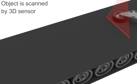
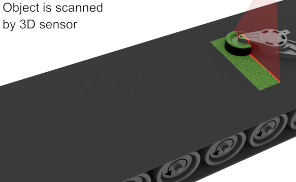
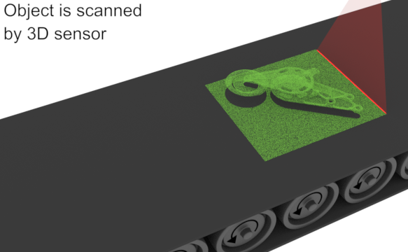
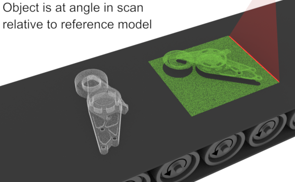
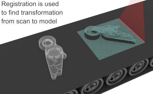
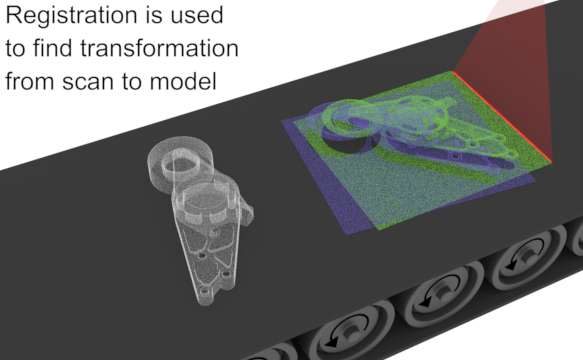
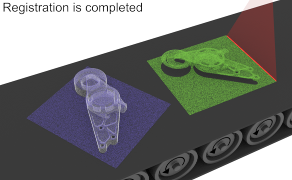
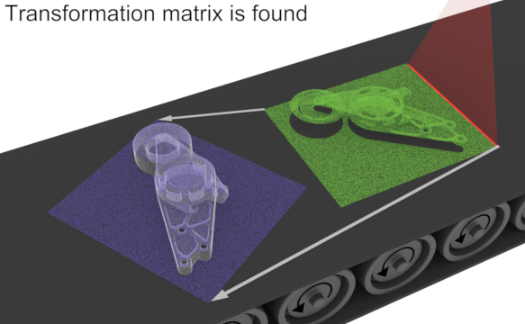
To generate the transformation coefficients required to fixture a scanned 3D object at an unknown orientation or position such that its points align with those of a reference object, you can use the 3D Registration module. First, perform 3D registration on the point cloud by calling M3dregCalculate(), which will calculate the transformation needed to achieve alignment between the source point cloud and its reference point cloud. Then, copy the registration matrix to a transformation matrix object using M3dregCopyResult() with M_REGISTRATION_MATRIX.
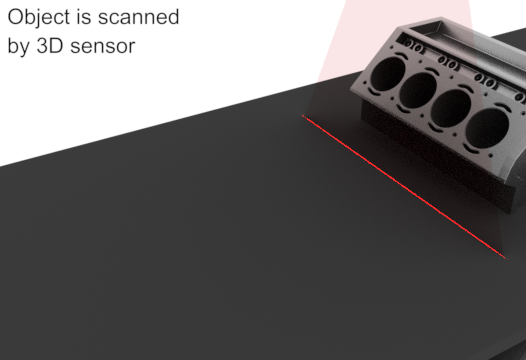
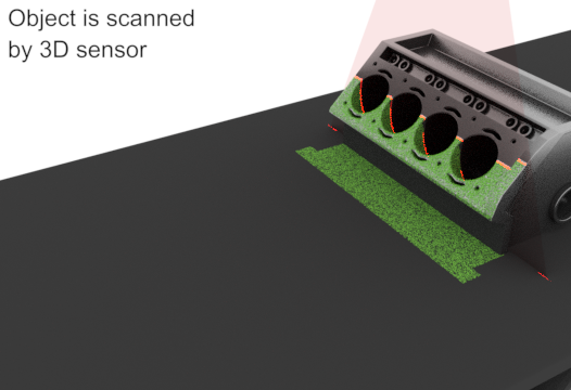
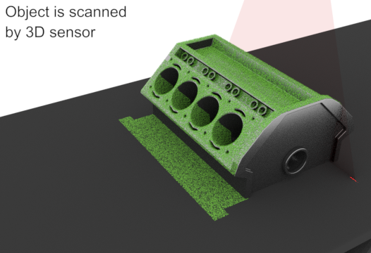
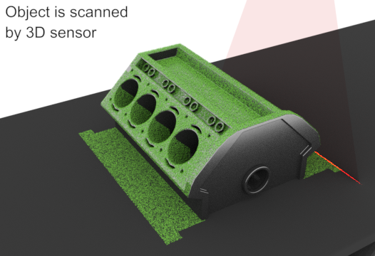
The following animation shows how to use 3D registration to fixture an object to a reference model:


The following code snippet is an example of the steps required to fixture to a reference object using the 3D Registration module:
MIL_ID MilPointCloudArray[2] = { ModelPointCloud, ObjectPointCloud };
MIL_ID MilRegResult = M3dregAllocResult(MilSystem, M_PAIRWISE_REGISTRATION_RESULT, M_DEFAULT, M_NULL);

/* Set the preregistration mode to align the centroids of the two point clouds. */
M3dregControl(MilContext, M_DEFAULT, M_PREREGISTRATION_MODE, M_CENTROID);

/* Perform registration and write the resulting transformation matrix into a result buffer. */
M3dregCalculate(MilContext,
  MilPointCloudArray,
  2,
  MilRegResult,
  M_DEFAULT);

/* Allocate a transformation matrix object and copy the registration matrix into it. */
MIL_ID MatrixId = M3dgeoAlloc(M_DEFAULT_HOST, M_TRANSFORMATION_MATRIX, M_DEFAULT, M_NULL);
M3dregCopyResult(MilRegResult, 1, 0, MatrixId, M_REGISTRATION_MATRIX, M_DEFAULT);

/* Apply the transformation matrix to the point cloud and store it in another point cloud. */
M3dimMatrixTransform(ObjectPointCloud, MilFixturedPointCloud, MatrixId, M_DEFAULT);
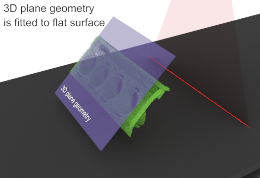
Fixturing to a plane
To generate the transformation coefficients required to fixture a point cloud to a plane, you can use the 3D Metrology module. For example, if the surface on which an object is scanned is at a slant, you can fit a plane to the surface, and then fixture subsequent scanned objects to that plane, such that they are no longer at a slant.
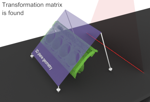
To obtain a point cloud of only the slanted surface, either scan the surface without the object, or mask out the object from an existing scan. You can then fit a plane to the surface using M3dmetFit() with M_PLANE, which will generate the transformation coefficients required to fixture a point cloud to the plane. Then, copy the fixturing matrix of the fitted plane to a transformation matrix object using M3dmetCopyResult() with M_FIXTURING_MATRIX.
The following code snippet is an example of the steps required to fixture to a plane using the 3D Metrology module:
/* Mask out the object. */
M3dimCrop(MilPtCldContainer, MilPtCldContainer, MilBox, M_NULL, M_DEFAULT, M_INVERSE);
/* Fit a plane to the point cloud. */
M3dmetFit(M_DEFAULT, MilPtCldContainer, M_PLANE, MilFitResult, M_INFINITE, M_DEFAULT);
/* Check if the fit was successful. */
M3dmetGetResult(MilFitResult, M_STATUS, &Status);
if (Status == M_SUCCESS)
{
/* Allocate a transformation matrix object and copy the fit results into it. */
MilFixturingMatrix = M3dgeoAlloc(MilSystem, M_TRANSFORMATION_MATRIX, M_DEFAULT, M_UNIQUE_ID);
M3dmetCopyResult(MilFitResult, MilFixturingMatrix, M_FIXTURING_MATRIX, M_DEFAULT);
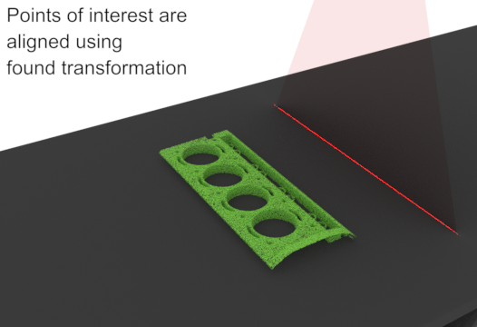
/* Apply the transformation matrix to the point cloud of a scanned object. */
M3dimMatrixTransform(PtCldObject, PtCldObject, MilFixturingMatrix, M_DEFAULT);
}
Another possible application for fixturing to a plane is when you have a scanned object that has a slanted region that you want to inspect. In this case, it might be useful to isolate and flatten the slant. To do so:
The following animation shows how to use the 3D Metrology module to fixture an object to a plane:


Applying a transformation matrix
Once you have a transformation matrix, you are ready to apply the transformation. If necessary, use M3dgeoMatrixSetTransform() with M_INVERSE to reverse the direction of the transformation, as transformation matrices are not bidirectional. Then, call M3dimMatrixTransform() to apply the transformation matrix to your point cloud. This will transform the points to the specified position and orientation and write them to a 3D MIL object of the same type as the specified point cloud container.