M3dgeoMatrixSetTransform
- See also

 Availability
 Function map
- Examples
 M3dgeoMatrixPut
- M3dgeoMatrixSetWithAxes

| MIL_ID Matrix3dgeoId, | //in |
| MIL_INT64 TransformType, | //in |
| MIL_DOUBLE Param1, | //in |
| MIL_DOUBLE Param2, | //in |
| MIL_DOUBLE Param3, | //in |
| MIL_DOUBLE Param4, | //in |
| MIL_INT64 ControlFlag | //in |
This function assigns a transformation to a transformation matrix object or composes a transformation with a transformation matrix object. The transformation can be defined as a translation, rotation, scale, or the result of a matrix composition.
Note that all angles should be given in degrees. However, unlike most other MIL functions, angles are interpreted using the right-hand grip rule around the axis of rotation; if you wrap your right hand around the axis of rotation, pointing your thumb in the positive direction of the axis, your fingers wrap in the direction of rotation. For example, a positive rotation around the Z-axis corresponds to a rotation that turns the positive X-axis toward the positive Y-axis.
All coordinates are expressed in world units in the working coordinate system.
Specifies the identifier of the transformation matrix object. The transformation matrix object must have been previously allocated using M3dgeoAlloc() with M_TRANSFORMATION_MATRIX.
Specifies the type of transformation to apply.
See the Parameter associations section for possible values that can be specified.
Specifies the first parameter used to define the transformation matrix.
See the Parameter associations section for possible values that can be specified.
Specifies the second parameter used to define the transformation matrix.
Set this parameter to M_DEFAULT if not used.
See the Parameter associations section for possible values that can be specified.
Specifies the third parameter used to define the transformation matrix.
Set this parameter to M_DEFAULT if not used.
See the Parameter associations section for possible values that can be specified.
Specifies the fourth parameter used to define the transformation matrix.
Set this parameter to M_DEFAULT if not used.
See the Parameter associations section for possible values that can be specified.
Specifies how to apply the transformation.
|
For specifying how to apply the
transformation |
|||||||||||||||||||||||||||||||||||||||
| Description | |||||||||||||||||||||||||||||||||||||||
|
Same as M_ASSIGN. |
|||||||||||||||||||||||||||||||||||||||
|
Specifies to assign the specified transformation to the given transformation matrix object. |
|||||||||||||||||||||||||||||||||||||||
|
Specifies to compose the specified transformation with the given matrix. The matrix composition follows the equation AB = C, where A is the transformation matrix specified by Matrix3dgeoId, B is the transformation matrix defined by the parameter associations, and C is the resulting transformation matrix. The values of the resulting transformation matrix are written to the transformation matrix object specified by Matrix3dgeoId. Note that transformation matrix B is applied before transformation matrix A. Therefore, transformation matrix C describes the transformation obtained by applying transformation matrix B followed by transformation matrix A. (summarize)Specifies to compose the specified transformation with the given matrix. (more details...) |
|||||||||||||||||||||||||||||||||||||||
The table below lists possible values for the TransformType, Param1, Param2, Param3, and Param4 parameters.
Set unused parameters to M_DEFAULT.
|
For specifying the transformation type
|
|||||||||||||||||||||||||||||||||||||||
| Description | |||||||||||||||||||||||||||||||||||||||
| Param1 | |||||||||||||||||||||||||||||||||||||||
| Param2 | |||||||||||||||||||||||||||||||||||||||
| Param3 | |||||||||||||||||||||||||||||||||||||||
| Param4 | |||||||||||||||||||||||||||||||||||||||
|
Specifies the transformation resulting from the composition of two matrices. The matrix composition follows the equation AB = C, where A is the transformation matrix specified by Param1, B is the transformation matrix specified by Param2, and C is the resulting transformation matrix. Note that transformation matrix B is applied before transformation matrix A. Therefore, transformation matrix C describes the transformation obtained by applying transformation matrix B followed by transformation matrix A. (summarize)Specifies the transformation resulting from the composition of two matrices. (more details...) |
|||||||||||||||||||||||||||||||||||||||
|
Specifies the first source matrix (that is, source matrix A). (summarize)Specifies the first source matrix (that is, source matrix A). (more details...) |
|||||||||||||||||||||||||||||||||||||||
|
Specifies the identity matrix. |
|||||||||||||||||||||||||||||||||||||||
|
Specifies the identifier of a transformation matrix object. |
|||||||||||||||||||||||||||||||||||||||
|
Specifies the second source matrix (that is, source matrix B). (summarize)Specifies the second source matrix (that is, source matrix B). (more details...) |
|||||||||||||||||||||||||||||||||||||||
|
Specifies the identity matrix. |
|||||||||||||||||||||||||||||||||||||||
|
Specifies the identifier of a transformation matrix object. |
|||||||||||||||||||||||||||||||||||||||
|
Specifies a transformation that can move the working coordinate system to a 3D geometry object. (summarize)Specifies a transformation that can move the working coordinate system to a 3D geometry object. (more details...) |
|||||||||||||||||||||||||||||||||||||||
|
Specifies a 3D geometry object. (summarize)Specifies a 3D geometry object. (more details...) |
|||||||||||||||||||||||||||||||||||||||
|
Specifies a 3D box geometry object identifier previously allocated using M3dgeoAlloc() with M_GEOMETRY and successfully defined as a box. The result is the transformation that can move the working coordinate system such that its origin moves to the box's center, and the box's orientation is applied. (summarize)Specifies a 3D box geometry object identifier previously allocated using M3dgeoAlloc() with M_GEOMETRY and successfully defined as a box. (more details...) |
|||||||||||||||||||||||||||||||||||||||
|
Specifies a 3D cylinder geometry object identifier previously allocated using M3dgeoAlloc() with M_GEOMETRY and successfully defined as a cylinder. The result is the transformation that can move the working coordinate system such that its origin moves to the cylinder's start point, and the cylinder's central axis becomes the positive Z-axis. The rotation of the X- and Y-axis is determined by the minimal rotation that must be applied to align the positive Z-axis with the cylinder's central axis. (summarize)Specifies a 3D cylinder geometry object identifier previously allocated using M3dgeoAlloc() with M_GEOMETRY and successfully defined as a cylinder. (more details...) |
|||||||||||||||||||||||||||||||||||||||
|
Specifies a 3D plane geometry object identifier previously allocated using M3dgeoAlloc() with M_GEOMETRY and successfully defined as a plane. The result is the transformation that can move the working coordinate system such that its XY (Z=0) plane is moved to the specified plane, and the plane's normal becomes the positive Z-axis. The working coordinate system's origin is moved to the closest point on the plane (the projection). (summarize)Specifies a 3D plane geometry object identifier previously allocated using M3dgeoAlloc() with M_GEOMETRY and successfully defined as a plane. (more details...) |
|||||||||||||||||||||||||||||||||||||||
|
Specifies a 3D sphere geometry object identifier previously allocated using M3dgeoAlloc() with M_GEOMETRY and successfully defined as a sphere. The result is the transformation that can move the working coordinate system such that its origin is moved to the sphere's center. No rotation is applied. (summarize)Specifies a 3D sphere geometry object identifier previously allocated using M3dgeoAlloc() with M_GEOMETRY and successfully defined as a sphere. (more details...) |
|||||||||||||||||||||||||||||||||||||||
|
Specifies a transformation that can move the XY (Z=0) plane of the working coordinate system to a plane specified by Param1. By default, the origin is moved using the same transformation. You can optionally specify a point on the plane where the origin should be moved, using Param2, Param3, and Param4. If the point is not on the plane, or if you set Param2, Param3, and Param4 to M_DEFAULT, the closest point on the plane (the projection) is chosen instead. (summarize)Specifies a transformation that can move the XY (Z=0) plane of the working coordinate system to a plane specified by Param1. (more details...) |
|||||||||||||||||||||||||||||||||||||||
|
Specifies a 3D geometry plane. (summarize)Specifies a 3D geometry plane. (more details...) |
|||||||||||||||||||||||||||||||||||||||
|
Specifies the XY (Z=0) plane. The result is the transformation that can move the origin of the working coordinate system to a point on its XY (Z=0) plane, specified by Param2, Param3, and Param4. If these parameters are set to M_DEFAULT, the result is the identity transformation. (summarize)Specifies the XY (Z=0) plane. (more details...) |
|||||||||||||||||||||||||||||||||||||||
|
Specifies a 3D plane geometry object identifier previously allocated using M3dgeoAlloc() with M_GEOMETRY and successfully defined as a plane. |
|||||||||||||||||||||||||||||||||||||||
|
Specifies the X-coordinate of a point on the plane where the origin will be moved. |
|||||||||||||||||||||||||||||||||||||||
|
Specifies the Y-coordinate of a point on the plane where the origin will be moved. |
|||||||||||||||||||||||||||||||||||||||
|
Specifies the Z-coordinate of a point on the plane where the origin will be moved. |
|||||||||||||||||||||||||||||||||||||||
|
Specifies the identity transformation. This resets the matrix to the identity matrix, removing all transformations from the transformation matrix object, when ControlFlag is M_ASSIGN. (summarize)Specifies the identity transformation. (more details...) |
|||||||||||||||||||||||||||||||||||||||
|
Specifies the inverse transformation. (summarize)Specifies the inverse transformation. (more details...) |
|||||||||||||||||||||||||||||||||||||||
|
Specifies the source matrix. (summarize)Specifies the source matrix. (more details...) |
|||||||||||||||||||||||||||||||||||||||
|
Specifies the identifier of a transformation matrix object previously allocated using M3dgeoAlloc() with M_TRANSFORMATION_MATRIX. |
|||||||||||||||||||||||||||||||||||||||
|
Specifies a rotation described by an axis and angle of rotation. The axis of rotation is defined by a vector. The angle of rotation is measured in the counter-clockwise direction around the axis of rotation. INQ 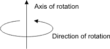
Specifies a rotation described by an axis and angle of rotation. INQ (more details...) |
|||||||||||||||||||||||||||||||||||||||
|
Specifies the X-component of the vector that defines the axis of rotation. |
|||||||||||||||||||||||||||||||||||||||
|
Specifies the Y-component of the vector that defines the axis of rotation. |
|||||||||||||||||||||||||||||||||||||||
|
Specifies the Z-component of the vector that defines the axis of rotation. |
|||||||||||||||||||||||||||||||||||||||
|
Specifies the angle of the rotation, in degrees, around the axis of rotation. (summarize)Specifies the angle of the rotation, in degrees, around the axis of rotation. (more details...) |
|||||||||||||||||||||||||||||||||||||||
|
Specifies the minimal rotation that can align the working coordinate system's X-axis with the specified vector. INQ (summarize)Specifies the minimal rotation that can align the working coordinate system's X-axis with the specified vector. INQ (more details...) |
|||||||||||||||||||||||||||||||||||||||
|
Specifies the X-component of the vector. |
|||||||||||||||||||||||||||||||||||||||
|
Specifies the Y-component of the vector. |
|||||||||||||||||||||||||||||||||||||||
|
Specifies the Z-component of the vector. |
|||||||||||||||||||||||||||||||||||||||
|
Specifies the minimal rotation that can align the working coordinate system's Y-axis with the specified vector. INQ (summarize)Specifies the minimal rotation that can align the working coordinate system's Y-axis with the specified vector. INQ (more details...) |
|||||||||||||||||||||||||||||||||||||||
|
Specifies the X-component of the vector. |
|||||||||||||||||||||||||||||||||||||||
|
Specifies the Y-component of the vector. |
|||||||||||||||||||||||||||||||||||||||
|
Specifies the Z-component of the vector. |
|||||||||||||||||||||||||||||||||||||||
|
Specifies the minimal rotation that can align the working coordinate system's Z-axis with the specified vector. INQ (summarize)Specifies the minimal rotation that can align the working coordinate system's Z-axis with the specified vector. INQ (more details...) |
|||||||||||||||||||||||||||||||||||||||
|
Specifies the X-component of the vector. |
|||||||||||||||||||||||||||||||||||||||
|
Specifies the Y-component of the vector. |
|||||||||||||||||||||||||||||||||||||||
|
Specifies the Z-component of the vector. |
|||||||||||||||||||||||||||||||||||||||
|
Specifies a rotation operation that is described by a rotation quaternion. INQ (summarize)Specifies a rotation operation that is described by a rotation quaternion. INQ (more details...) |
|||||||||||||||||||||||||||||||||||||||
|
Specifies the scalar component of the quaternion. |
|||||||||||||||||||||||||||||||||||||||
|
Specifies the X-component of the quaternion. |
|||||||||||||||||||||||||||||||||||||||
|
Specifies the Y-component of the quaternion. |
|||||||||||||||||||||||||||||||||||||||
|
Specifies the Z-component of the quaternion. |
|||||||||||||||||||||||||||||||||||||||
|
Specifies a rotation operation around the X-axis. (summarize)Specifies a rotation operation around the X-axis. (more details...) |
|||||||||||||||||||||||||||||||||||||||
|
Specifies the X-axis rotation, in degrees. (summarize)Specifies the X-axis rotation, in degrees. (more details...) |
|||||||||||||||||||||||||||||||||||||||
|
Specifies a rotation that is described by three distinct rotations about the axes of the working coordinate system in the following order: a rotation about the X-axis, a rotation about the Y-axis, and a rotation about the Z-axis rotation. INQ (summarize)Specifies a rotation that is described by three distinct rotations about the axes of the working coordinate system in the following order: a rotation about the X-axis, a rotation about the Y-axis, and a rotation about the Z-axis rotation. INQ (more details...) |
|||||||||||||||||||||||||||||||||||||||
|
Specifies the X-axis rotation, in degrees. (summarize)Specifies the X-axis rotation, in degrees. (more details...) |
|||||||||||||||||||||||||||||||||||||||
|
Specifies the Y-axis rotation, in degrees. (summarize)Specifies the Y-axis rotation, in degrees. (more details...) |
|||||||||||||||||||||||||||||||||||||||
|
Specifies the Z-axis rotation, in degrees. (summarize)Specifies the Z-axis rotation, in degrees. (more details...) |
|||||||||||||||||||||||||||||||||||||||
|
Specifies a rotation that is described by three distinct rotations about the axes of the working coordinate system in the following order: a rotation about the X-axis, a rotation about the Z-axis, and a rotation about the Y-axis rotation. INQ (summarize)Specifies a rotation that is described by three distinct rotations about the axes of the working coordinate system in the following order: a rotation about the X-axis, a rotation about the Z-axis, and a rotation about the Y-axis rotation. INQ (more details...) |
|||||||||||||||||||||||||||||||||||||||
|
Specifies the X-axis rotation, in degrees. (summarize)Specifies the X-axis rotation, in degrees. (more details...) |
|||||||||||||||||||||||||||||||||||||||
|
Specifies the Z-axis rotation, in degrees. (summarize)Specifies the Z-axis rotation, in degrees. (more details...) |
|||||||||||||||||||||||||||||||||||||||
|
Specifies the Y-axis rotation, in degrees. (summarize)Specifies the Y-axis rotation, in degrees. (more details...) |
|||||||||||||||||||||||||||||||||||||||
|
Specifies a rotation operation around the Y-axis. (summarize)Specifies a rotation operation around the Y-axis. (more details...) |
|||||||||||||||||||||||||||||||||||||||
|
Specifies the Y-axis rotation, in degrees. (summarize)Specifies the Y-axis rotation, in degrees. (more details...) |
|||||||||||||||||||||||||||||||||||||||
|
Specifies a rotation that is described by three distinct rotations about the axes of the working coordinate system in the following order: a rotation about the Y-axis, a rotation about the X-axis, and a rotation about the Z-axis rotation. INQ (summarize)Specifies a rotation that is described by three distinct rotations about the axes of the working coordinate system in the following order: a rotation about the Y-axis, a rotation about the X-axis, and a rotation about the Z-axis rotation. INQ (more details...) |
|||||||||||||||||||||||||||||||||||||||
|
Specifies the Y-axis rotation, in degrees. (summarize)Specifies the Y-axis rotation, in degrees. (more details...) |
|||||||||||||||||||||||||||||||||||||||
|
Specifies the X-axis rotation, in degrees. (summarize)Specifies the X-axis rotation, in degrees. (more details...) |
|||||||||||||||||||||||||||||||||||||||
|
Specifies the Z-axis rotation, in degrees. (summarize)Specifies the Z-axis rotation, in degrees. (more details...) |
|||||||||||||||||||||||||||||||||||||||
|
Specifies a rotation that is described by three distinct rotations about the axes of the working coordinate system in the following order: a rotation about the Y-axis, a rotation about the Z-axis, and a rotation about the X-axis rotation. INQ (summarize)Specifies a rotation that is described by three distinct rotations about the axes of the working coordinate system in the following order: a rotation about the Y-axis, a rotation about the Z-axis, and a rotation about the X-axis rotation. INQ (more details...) |
|||||||||||||||||||||||||||||||||||||||
|
Specifies the Y-axis rotation, in degrees. (summarize)Specifies the Y-axis rotation, in degrees. (more details...) |
|||||||||||||||||||||||||||||||||||||||
|
Specifies the Z-axis rotation, in degrees. (summarize)Specifies the Z-axis rotation, in degrees. (more details...) |
|||||||||||||||||||||||||||||||||||||||
|
Specifies the X-axis rotation, in degrees. (summarize)Specifies the X-axis rotation, in degrees. (more details...) |
|||||||||||||||||||||||||||||||||||||||
|
Specifies a rotation operation around the Z-axis. (summarize)Specifies a rotation operation around the Z-axis. (more details...) |
|||||||||||||||||||||||||||||||||||||||
|
Specifies the Z-axis rotation, in degrees. (summarize)Specifies the Z-axis rotation, in degrees. (more details...) |
|||||||||||||||||||||||||||||||||||||||
|
Specifies a rotation that is described by three distinct rotations about the axes of the working coordinate system in the following order: a rotation about the Z-axis, a rotation about the X-axis, and a rotation about the Y-axis rotation. INQ (summarize)Specifies a rotation that is described by three distinct rotations about the axes of the working coordinate system in the following order: a rotation about the Z-axis, a rotation about the X-axis, and a rotation about the Y-axis rotation. INQ (more details...) |
|||||||||||||||||||||||||||||||||||||||
|
Specifies the Z-axis rotation, in degrees. (summarize)Specifies the Z-axis rotation, in degrees. (more details...) |
|||||||||||||||||||||||||||||||||||||||
|
Specifies the X-axis rotation, in degrees. (summarize)Specifies the X-axis rotation, in degrees. (more details...) |
|||||||||||||||||||||||||||||||||||||||
|
Specifies the Y-axis rotation, in degrees. (summarize)Specifies the Y-axis rotation, in degrees. (more details...) |
|||||||||||||||||||||||||||||||||||||||
|
Specifies a rotation that is described by three distinct rotations about the axes of the working coordinate system in the following order: a rotation about the Z-axis, a rotation about the Y-axis, and a rotation about the X-axis rotation. INQ (summarize)Specifies a rotation that is described by three distinct rotations about the axes of the working coordinate system in the following order: a rotation about the Z-axis, a rotation about the Y-axis, and a rotation about the X-axis rotation. INQ (more details...) |
|||||||||||||||||||||||||||||||||||||||
|
Specifies the Z-axis rotation, in degrees. (summarize)Specifies the Z-axis rotation, in degrees. (more details...) |
|||||||||||||||||||||||||||||||||||||||
|
Specifies the Y-axis rotation, in degrees. (summarize)Specifies the Y-axis rotation, in degrees. (more details...) |
|||||||||||||||||||||||||||||||||||||||
|
Specifies the X-axis rotation, in degrees. (summarize)Specifies the X-axis rotation, in degrees. (more details...) |
|||||||||||||||||||||||||||||||||||||||
|
Specifies a scaling operation. INQ (summarize)Specifies a scaling operation. INQ (more details...) |
|||||||||||||||||||||||||||||||||||||||
|
Specifies the scaling factor in X. |
|||||||||||||||||||||||||||||||||||||||
|
Specifies the scaling factor in Y. |
|||||||||||||||||||||||||||||||||||||||
|
Specifies the scaling factor in Z. |
|||||||||||||||||||||||||||||||||||||||
|
Specifies a translation along each of the axes of the working coordinate system. INQ (summarize)Specifies a translation along each of the axes of the working coordinate system. INQ (more details...) |
|||||||||||||||||||||||||||||||||||||||
|
Specifies the displacement along the X-axis. |
|||||||||||||||||||||||||||||||||||||||
|
Specifies the displacement along the Y-axis. |
|||||||||||||||||||||||||||||||||||||||
|
Specifies the displacement along the Z-axis. |
|||||||||||||||||||||||||||||||||||||||
| Header | Include mil.h. |
| Library | Use mil.lib; mil3d.lib. |
| DLL | Requires mil.dll; mil3d.dll. |