Using I/O command lists
- See also

 Availability
 Previous
- Next

-
Allocate an I/O command list using MsysIoAlloc() with M_IO_COMMAND_LIST. You can allocate as many command lists as are available on your hardware product. When allocating an I/O command list, you must specify a signal as the counter source that will be used to schedule commands. The counter source can be either a clock, which allows you to schedule commands in time, or a specified signal, which allows you to schedule commands based on the number of transitions that occur on the signal. The latter case allows you to schedule commands, for example, based on the positional information provided by the output signal of your hardware product's rotary decoder (that is, distance).
-
If necessary, route the state of the bits of the I/O command list's register to auxiliary output signals using MsysControl() with M_IO_SOURCE. This register is referred to as an I/O command register.
-
If necessary, enable the use of one of the I/O command list's latches using MsysIoControl() with the M_REFERENCE_LATCH_... constants. Latches are used to store a timestamp or counter value upon the specified transition of a specified signal. You can then use this timestamp or counter value to schedule commands relative to this event.
-
Add commands to the I/O command list using MsysIoCommandRegister(). Commands will change the state of a bit of the I/O command register at a specified time or counter value. Multiple I/O command register bits can be changed at a single moment. Commands can be added in any order.
-
Free your I/O command list using MsysIoFree().
-
Cause a rising edge (M_EDGE_RISING). Changes the specified bit such that the associated signal will transition from low to high, if it is low.
-
Cause a falling edge (M_EDGE_FALLING). Changes the specified bit such that the associated signal will transition from high to low, if it is high.
-
Cause an active high pulse (M_PULSE_HIGH). This command actually adds two commands to the list: an M_EDGE_RISING followed by an M_EDGE_FALLING command a specified duration afterwards.
-
Cause an active low pulse (M_PULSE_LOW). This command actually adds two commands to the list: an M_EDGE_FALLING followed by an M_EDGE_RISING command a specified duration afterwards.
-
Cause a very short active high pulse (M_IMPULSE). Unlike M_PULSE_HIGH, a single command producing the shortest possible pulse is added to the list. This operation should not be output to external devices since it might be filtered out as noise. It can, however, be used to trigger internal hardware devices, such as timers.
-
Always grabbing an image when the conveyor belt is at a given position.
-
Parts traveling along a conveyor belt that are fixed in position.
-
Different parts traveling along a conveyor belt that are ejected by different devices.
-
Parts traveling along a conveyor belt that are not fixed in position.
Some Matrox hardware products have I/O command lists (for example, Matrox 4Sight GPm). I/O command lists allow you to schedule changing the state of a bit of an I/O command register at a specified time or counter value. You can route the state of the bit, for example, to an auxiliary output signal to control a connected device at a required moment; the state of the bit can also be used to trigger some other internal device (for example, a timer). An I/O command list allows you to schedule I/O commands in any order. You can allocate and control an I/O command list using the MsysIo...() functions.
Steps to use an I/O command list
The following steps provide a basic methodology for using an I/O command list on a Matrox hardware product:
Scheduling I/O commands
The commands in the list are executed at a specified moment. To schedule commands, the I/O command list uses an internal counter to count clock ticks or transitions that occur on a signal specified as the counter source. The counter source is specified when you allocate the I/O command list using MsysIoAlloc(). The counter source can be a clock, an auxiliary signal, or the output signal of a rotary decoder.
You schedule commands by specifying a delay from a specific reference moment. For the reference moment, you can inquire the counter value at a specific moment through software using MsysIoInquire() with M_REFERENCE_VALUE. Alternatively, you can use an I/O command list's latch to store the counter value at the moment of a hardware event; for more information, see the Using an I/O command list latch subsection of this section.
If the I/O command list was allocated using a clock as the counter source (using MsysIoAlloc() with M_CLOCK), the internal counter counts the clock ticks and you schedule commands a certain amount of time, in seconds, after the reference moment. For example, you can schedule the command to execute 10 msec (0.01 sec) after a previously inquired reference moment.
// Allocate a command list based on the internal clock
MsysIoAlloc(SysId, M_IO_COMMAND_LIST1, M_IO_COMMAND_LIST, M_CLOCK, &CmdListId);

// Route the state of the I/O command list's register bits to auxiliary output signals
MsysControl(SysId, M_IO_SOURCE+M_AUX_IO0, M_IO_COMMAND_LIST1 + M_IO_COMMAND_BIT0);
MsysControl(SysId, M_IO_SOURCE+M_AUX_IO1, M_IO_COMMAND_LIST1 + M_IO_COMMAND_BIT1);
MsysControl(SysId, M_IO_SOURCE+M_AUX_IO2, M_IO_COMMAND_LIST1 + M_IO_COMMAND_BIT2);
MsysControl(SysId, M_IO_SOURCE+M_AUX_IO3, M_IO_COMMAND_LIST1 + M_IO_COMMAND_BIT3);

// Add a command to the I/O command list to immediately change the state of M_IO_COMMAND_BIT0
// such that a low to high signal transition occurs on M_AUX_IO0
MsysIoCommandRegister(CmdListId, M_EDGE_RISING, M_REFERENCE_VALUE_CURRENT,
                                               0, M_DEFAULT, M_IO_COMMAND_BIT0, M_NULL);

// Add a command to the I/O command list to change the state of M_IO_COMMAND_BIT0 10 ms
// after the function is called such that a high to low signal transition occurs on M_AUX_IO0
MsysIoCommandRegister(CmdListId, M_EDGE_FALLING, M_REFERENCE_VALUE_CURRENT,
                                           0.010, M_DEFAULT, M_IO_COMMAND_BIT0, M_NULL);

// Inquire the current timestamp so that it can be used as a reference point
MsysIoInquire(CmdListId, M_REFERENCE_VALUE, &ReferenceStamp);

// Add a command to the I/O command list to change the state of M_IO_COMMAND_BIT3 15 ms
// after the above reference moment, such that a positive 3 ms pulse occurs on M_AUX_IO3
MsysIoCommandRegister(CmdListId, M_PULSE_HIGH, ReferenceStamp, 0.015, 0.003,
                                                M_IO_COMMAND_BIT3, M_NULL);

// ...

// Free the I/O command list
MsysIoFree(CmdListId);
If the I/O command list was allocated using MsysIoAlloc() with M_AUX_IOn or M_ROTARY_ENCODERn as the counter source, the internal counter counts the number of signal transitions on the signal (by default, low-to-high signal transitions). For example, if you are using a rotary decoder's output signal as your counter source, you would schedule your commands based on the positional information provided by the signal (that is, distance). If your rotary decoder is set up to output a pulse each time a conveyor belt moves forward a step (MsysControl() with M_ROTARY_ENCODER_OUTPUT_MODE set to M_STEP_FORWARD), you can, for example, add a command that should be executed a constant number of forward steps after an object on the conveyor belt passes in front of a sensor. To set up a rotary decoder so that it outputs a pulse after a specific distance or when moving forward new steps (ignoring forward steps that occurred to return to an original position after an unplanned rotary displacement in the reverse direction occurs), see the Using quadrature input from a rotary encoder section earlier in this chapter.
If a command has been added to the I/O command list to modify a specific bit of the I/O command register, and you attempt to add a different command to operate on the same bit at the same moment, the original entry will be overwritten. However, multiple commands can be added to execute at the same moment, as long as the commands are affecting different I/O command register bits.
Commands that can be added to the I/O command list
Using the MsysIoCommandRegister() function, you can add the following commands to an I/O command list:
When adding a command to change an I/O command register bit such that a pulse is generated on the associated signal, two commands are actually added; one command to transition the signal at the specified moment and one command to transition the signal back to its original state after the specified pulse duration. Note that if you want to specify the duration of the pulse in seconds, but the counter source is not a clock (that is, the CounterSrc parameter of MsysIoAlloc() was set to anything other than M_CLOCK), use a timer to generate the pulse and the I/O command list to trigger the timer to generate the pulse; in this case, schedule an M_IMPULSE command and use the affected I/O command register bit as the trigger source of a timer.
// Allocate a command list based on the rotary decoder's output signal
MsysIoAlloc(SysId, M_IO_COMMAND_LIST1, M_IO_COMMAND_LIST, M_ROTARY_ENCODER1, &CmdListId);

// Setup timer
MsysControl(SysId, M_TIMER_DELAY + M_TIMER1, 0);
MsysControl(SysId, M_TIMER_DURATION + M_TIMER1, 10000000); //time in nsec
MsysControl(SysId, M_TIMER_TRIGGER_SOURCE + M_TIMER1, M_IO_COMMAND_LIST1 + M_IO_COMMAND_BIT1);
MsysControl(SysId, M_TIMER_STATE + M_TIMER1, M_ENABLE);

// Trigger the timer with an M_IMPULSE command 50 rotary decoder pulses after a specific moment;
// this will cause the timer to output a pulse of 10 msecs
MsysIoCommandRegister(CmdListId, M_IMPULSE, ReferenceStamp, 50, M_DEFAULT, M_IO_COMMAND_BIT1, M_NULL);
If you always want the command to change an I/O command register bit, use the + M_AUTO_REGISTER. Rather than waiting on a specified condition, the I/O command register bit is changed every time the latch is triggered. Note that, M_AUTO_REGISTER must be used with M_LATCHn.
Using an I/O command list latch
Each I/O command list on your Matrox hardware product has at least two latches that can be used to store the value of the command list's internal counter in hardware, upon a signal transition of a specified input signal. Using the latch, you can obtain the counter value at a particular moment; this is more precise than inquiring it in software using MsysIoInquire() with M_REFERENCE_VALUE. The counter value is stored in the latch until another signal transition occurs, which will overwrite the contents of the latch. To retrieve the latch's content, use MsysIoInquire() with M_REFERENCE_LATCH_VALUE or, if within the scope of a system hook-handler function, use MsysGetHookInfo() with M_REFERENCE_LATCH_VALUE.

To enable the use of a latch, use MsysIoControl() with M_REFERENCE_LATCH_STATE. To change the input signal which triggers storing the counter value, use MsysIoControl() with M_REFERENCE_LATCH_TRIGGER_SOURCE. To change the signal transition upon which to store the counter value in the latch, use MsysIoControl() with M_REFERENCE_LATCH_ACTIVATION.
As mentioned, if another signal transition occurs on the specified input signal, the contents of the latch will be overwritten with the counter value of that moment. To store the latch's contents in software (for example, into a queue) before it is overwritten, you can allow the specified input signal to generate an interrupt and hook a function to this event which retrieves the counter value stored by the latch. To enable interrupt generation on a signal, use MsysControl() with M_IO_INTERRUPT_STATE. To attach a hook-handler function to an I/O interrupt event, use MsysHookFunction() with M_IO_CHANGE. To retrieve the counter value stored by the latch in the hook-handler function, use MsysGetHookInfo() with M_REFERENCE_LATCH_VALUE.
Examples
The I/O command list can be used for many applications. The following sub-sections present 4 possible applications:
Always grabbing an image when the conveyor belt is at a given position
In this example, parts are moving along a conveyor belt but are fixed in their position on the conveyor belt. The parts are always taking 100 rotary encoder steps forward before reaching a camera, which will take a picture of the conveyor belt beneath it. For simplicity, the conveyor belt can only move forward and the camera is an areascan camera. A sensor detects each time a part is on the conveyor belt, and a rotary encoder is used to tell the camera when the part is best placed to take the picture. The camera is triggered by a rising pulse.
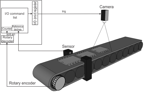
An I/O command list is used to cause the camera's trigger to activate. The rotary decoder output is used as the counter source of the I/O command list so that scheduling of commands is based on a specified number of rotary encoder steps (distance that the part travels). A latch stores the value of the command list's internal counter automatically after 100 rotary encoder steps. Once the latch fires, the camera trigger's pulse rises, and a grab occurs. When the grab is complete, some processing is performed. This process repeats for each part passing the sensor. By using M_AUTO_REGISTER with a registered command, you guarantee that every time the latch fires, a grab will occur.
// M_AUX_IO14: Receives rotary encoder bit 0
// M_AUX_IO15: Receives rotary encoder bit 1
// M_AUX_IO8 (input): Object detector
// M_AUX_IO0 (output): trigger to the camera, 100 positions after object detector
#define CAMERA_TRIGGER_OFFSET 100   // in rotary encoder steps

MIL_INT MFTYPE ProcessingFunction(MIL_INT HookType, MIL_ID HookId, void* HookDataPtr);

typedef struct _HOOK_PARAM
{
   MIL_ID MilSystem;
   MIL_ID CmdListId;
} HOOK_PARAM, *PHOOK_PARAM;
    // Setup triggered grab.
    MdigControl(MilDigitizer, M_GRAB_TRIGGER_SOURCE, M_AUX_IO0);
    MdigControl(MilDigitizer, M_GRAB_TRIGGER_ACTIVATION, M_EDGE_RISING);
    MdigControl(MilDigitizer, M_GRAB_TRIGGER_STATE, M_ENABLE);

    // Setup the rorary decoder; for simplicty, we assume the conveyor cannot move backwards.
    MsysControl(SysId, M_ROTARY_ENCODER_BIT0_SOURCE + M_ROTARY_ENCODER1, M_AUX_IO14);
    MsysControl(SysId, M_ROTARY_ENCODER_BIT1_SOURCE + M_ROTARY_ENCODER1, M_AUX_IO15);
    MsysControl(SysId, M_ROTARY_ENCODER_OUTPUT_MODE + M_ROTARY_ENCODER1, M_STEP_FORWARD);
    MsysControl(SysId, M_ROTARY_ENCODER_STATE + M_ROTARY_ENCODER1, M_ENABLE);

    // Link the grab trigger to an I/O command register bit.
    MsysControl(SysId, M_IO_SOURCE + M_AUX_IO0, M_IO_COMMAND_LIST1 + M_IO_COMMAND_BIT0);

    // Allocate an I/O command list where I/O commands are scheduled based on rotary decoder 1's output signal.
    CmdListId = MsysIoAlloc(SysId, M_IO_COMMAND_LIST1, M_IO_COMMAND_LIST, M_ROTARY_ENCODER1, M_NULL);
    if (CmdListId!= M_NULL)
    {

        // Latch the counter upon detection of the object
        MsysIoControl(CmdListId, M_REFERENCE_LATCH_TRIGGER_SOURCE+M_LATCH1, M_AUX_IO8);
        MsysIoControl(CmdListId, M_REFERENCE_LATCH_ACTIVATION+M_LATCH1, M_EDGE_RISING);
        MsysIoControl(CmdListId, M_REFERENCE_LATCH_STATE+M_LATCH1, M_ENABLE);

        // Every one hundred decoder steps after latch 1 is triggered, two I/O commands
        // are automatically added to the I/O command list to change register bit 0,
        // such that M_AUX_IO0 outputs an active high pulse.
        // Since M_AUX_IO0 is the grab trigger source, a frame will always be grabbed 100
        // decoder steps after latch 1 is triggered.
        MsysIoCommandRegister(CmdListId, M_PULSE_HIGH+M_AUTO_REGISTER, M_LATCH1, CAMERA_TRIGGER_OFFSET, 1, M_IO_COMMAND_BIT0, M_NULL);

        // Start the grabbing and processing.
        // The processing function is called each time a frame is grabbed.
        MdigProcess(MilDigitizer, MilGrabBufferList, MilGrabBufferListSize,
            M_START, M_DEFAULT, ProcessingFunction, &HookParam);

        // Print a message and wait for a key press before stopping the processing.
        MosPrintf(MIL_TEXT("Press <Enter> to stop.                    \n\n"));
        MosGetch();

        HookParam.MilSystem = SysId;
        HookParam.CmdListId = CmdListId;

        // Stop the grabbing and processing.
        MdigProcess(MilDigitizer, MilGrabBufferList, MilGrabBufferListSize,
            M_STOP, M_DEFAULT, ProcessingFunction, &HookParam);

        // Release the auto-register, so that, if latch 1 is triggered, it will not cause
        // an I/O command to be added.
        MsysIoCommandRegister(CmdListId, M_PULSE_HIGH + M_AUTO_REGISTER_CANCEL, M_LATCH1, CAMERA_TRIGGER_OFFSET, 1, M_IO_COMMAND_BIT0, M_NULL);

    }

  // Free the I/O command list.
    MsysIoFree(CmdListId);
Where the processing function is:
// Defines the processing function, called by MdigProcess()
MIL_INT MFTYPE ProcessingFunction(MIL_INT HookType, MIL_ID HookId, void* HookDataPtr)
   {
   PHOOK_PARAM pHookParam = (PHOOK_PARAM)HookDataPtr;
   MIL_ID ModifiedBufferId;

   /* Retrieve the MIL_ID of the grabbed buffer. */
   MdigGetHookInfo(HookId, M_MODIFIED_BUFFER+M_BUFFER_ID, &ModifiedBufferId);

   /* Execute the processing  */
   // ... PUT YOUR PROCESSING FUNCTION HERE

   return 0;
   }
Parts traveling along a conveyor belt that are fixed in position example
In this example, parts are moving along a conveyor belt but are fixed in their position on the conveyor belt. The parts are always taking 500 rotary encoder steps forward before reaching an ejector, which will discard the part if processing fails. For simplicity, the conveyor belt can only move forward and the camera is a frame-scan camera. A sensor detects each time a part is under the camera's field of view; the sensor's signal is used to trigger the grab. The ejector requires a pulse of 10 msec (0.01 sec) to successfully discard a part.

An I/O command list is used to schedule the ejection of a part if it fails processing. The rotary decoder output is used as the counter source of the I/O command list so that scheduling of commands is based on rotary encoder steps (distance that the part travels). A latch stores the value of the command list's internal counter upon the trigger signal from the sensor; the hooked function retrieves the counter value stored in the latch and adds it to a queue. When the grab is complete, some processing is performed and a decision is made to discard or keep the part. If the part must be discarded, a command is added to discard the part 500 rotary encoder steps after the grab started. The ejector requires a pulse of 10 msec; however, if you use MsysIoCommandRegister() with M_PULSE_HIGH to add a pulse command, you would need to specify the duration of the pulse in rotary decoder output signal transitions (in distance instead of time), since the rotary decoder output signal is the counter source. To specify the pulse duration in time so that it is the correct width, an M_IMPULSE command is added instead and a timer is also used; the M_IMPULSE command affects an I/O command register bit that triggers the timer that outputs a signal with an appropriate pulse.
// M_AUX_IO14: Receives rotary encoder bit 0
// M_AUX_IO15: Receives rotary encoder bit 1
// M_AUX_IO8 (input): Receives signal from sensor.
//                    sensor sends same signal to M_AUX_IO0 of camera/digitizer.
// M_AUX_IO1 (output): Sent to ejector from timer
// M_TIMER1: Generates ejector pulse. Timer used so can specify pulse duration
//           in time and moment to execute command in rotary decoder output counts.
#define PULSE_WIDTH         10000000   // 10 ms
#define EJECTOR_OFFSET      500        // rotary decoder output counts

static std::queue<MIL_INT64> ReferenceStamp;
static CRITICAL_SECTION FifoLock;
static MIL_ID CmdListId;
static MIL_ID SysId;
//...
InitializeCriticalSection(&FifoLock); //Initalizes mutex
// Setup triggered grab.
MdigControl(MilDigitizer, M_GRAB_TRIGGER_SOURCE, M_AUX_IO0); //camera/digitizer aux I/O (input)
MdigControl(MilDigitizer, M_GRAB_TRIGGER_ACTIVATION, M_EDGE_RISING);
MdigControl(MilDigitizer, M_GRAB_TRIGGER_STATE, M_ENABLE);

// Setup rotary decoder; for simplicity, we assume the conveyor cannot move backward.
MsysControl(SysId, M_ROTARY_ENCODER_BIT0_SOURCE + M_ROTARY_ENCODER1, M_AUX_IO14);
MsysControl(SysId, M_ROTARY_ENCODER_BIT1_SOURCE + M_ROTARY_ENCODER1, M_AUX_IO15);
MsysControl(SysId, M_ROTARY_ENCODER_OUTPUT_MODE + M_ROTARY_ENCODER1, M_STEP_FORWARD);
MsysControl(SysId, M_ROTARY_ENCODER_STATE + M_ROTARY_ENCODER1, M_ENABLE);

// Setup ejector pulse.
MsysControl(SysId, M_IO_SOURCE + M_AUX_IO1, M_TIMER1);
MsysControl(SysId, M_TIMER_DELAY + M_TIMER1, 0);
MsysControl(SysId, M_TIMER_DURATION + M_TIMER1, PULSE_WIDTH);
MsysControl(SysId, M_TIMER_TRIGGER_SOURCE + M_TIMER1, M_IO_COMMAND_LIST1 + M_IO_COMMAND_BIT1);
MsysControl(SysId, M_TIMER_STATE + M_TIMER1, M_ENABLE);

// Allocate a command list where commands are scheduled based on rotary decoder 1's output signal.
MsysIoAlloc(SysId, M_IO_COMMAND_LIST1, M_IO_COMMAND_LIST, M_ROTARY_ENCODER1, &CmdListId);
if (CmdListId != M_NULL)
{
   // Latch counter upon detection of part
   MsysIoControl(CmdListId, M_REFERENCE_LATCH_TRIGGER_SOURCE + M_LATCH1, M_AUX_IO8);
   MsysIoControl(CmdListId, M_REFERENCE_LATCH_ACTIVATION + M_LATCH1, M_EDGE_RISING);
   MsysIoControl(CmdListId, M_REFERENCE_LATCH_STATE + M_LATCH1, M_ENABLE);

   // Hook a function to sensor's signal (M_AUX_IO8);
   // hook-handler function reads and queues latched value.
   MsysControl(SysId, M_IO_INTERRUPT_ACTIVATION + M_AUX_IO8, M_EDGE_RISING);
   MsysHookFunction(SysId, M_IO_CHANGE, &using_io_command_list_case_1::IoHookFunction, M_NULL);
   MsysControl(SysId, M_IO_INTERRUPT_STATE + M_AUX_IO8, M_ENABLE);

   // Start the grabbing and processing.
   // The processing function is called each time a frame is grabbed.
   MdigProcess(MilDigitizer, MilGrabBufferList, MilGrabBufferListSize,
      M_START, M_DEFAULT, &using_io_command_list_case_1::ProcessingFunction, M_NULL);

   // Print a message and wait for a key press before stopping the processing.
   MosPrintf(MIL_TEXT("Press <Enter> to stop.                    \n\n"));
   MosGetch();
   MdigProcess(MilDigitizer, MilGrabBufferList, MilGrabBufferListSize,
      M_STOP, M_DEFAULT, ProcessingFunction, M_NULL);
}
// ...
Where the function hooked to the I/O interrupt event and the processing function are:
// IO interrupt hook function to read and queue latched value so it can be used as
// the reference value to schedule a command for the newly grabbed part if necessary.
static MIL_INT MFTYPE IoHookFunction(MIL_INT HookType, MIL_ID EventId, void *UserDataPtr)
{
   MIL_INT PinNb = 0;
   MIL_INT64  RefStamp;

   // If the signal that called the hooked function is M_AUX_IO8.
   MsysGetHookInfo(SysId, EventId, M_IO_INTERRUPT_SOURCE, &PinNb);
   if (PinNb == M_AUX_IO8)
   {
      // Get and queue latched value.
      MsysGetHookInfo(SysId, EventId, M_REFERENCE_LATCH_VALUE + M_IO_COMMAND_LIST1 + M_LATCH1,
         &RefStamp);
      EnterCriticalSection(&FifoLock);
      ReferenceStamp.push(RefStamp);
      LeaveCriticalSection(&FifoLock);
   }
   return M_NULL;
}

//Each time a new frame is grabbed in a buffer, this function is called.
static MIL_INT MFTYPE ProcessingFunction(MIL_INT HookType, MIL_ID HookId, void* HookDataPtr)
{
   BOOL ShouldRejectTheObject = FALSE;
   MIL_INT64 RefStamp;
   MIL_ID ModifiedBufferId;

   /* Retrieve the MIL_ID of the grabbed buffer. */
   MdigGetHookInfo(HookId, M_MODIFIED_BUFFER + M_BUFFER_ID, &ModifiedBufferId);

   /* Execute the processing  */
   // ... PUT YOUR PROCESSING FUNCTION HERE AND SET ShouldRejectTheObject ACCORDINGLY

   // Reference latch FIFO should not be empty, but just in case.
   while (ReferenceStamp.empty())
      MosSleep(1);

   // Remove a latched value from the queue even if not ejecting.
   EnterCriticalSection(&FifoLock);
   RefStamp = ReferenceStamp.front();
   ReferenceStamp.pop();
   LeaveCriticalSection(&FifoLock);

   // If required, insert an ejection pulse after the proper distance.
   if (ShouldRejectTheObject)
      MsysIoCommandRegister(CmdListId, M_IMPULSE, RefStamp,
      EJECTOR_OFFSET, M_DEFAULT, M_IO_COMMAND_BIT1, M_NULL);
   return M_NULL;
}
Different parts traveling along a conveyor belt that are ejected by different devices example
In this example, three different parts are moving along a conveyor belt and each different part needs to be redirected to a different path. Three ejectors redirect the different parts to the correct path. Each ejector is a known distance away from a sensor that triggers the grab. Parts of type "A" are redirected by ejector A, which is 800 rotary encoder steps away from the sensor; parts of type "B" are redirected by ejector B, which is 1000 rotary encoder steps away from the sensor. Parts of type "C" are redirected by ejector C, which is 1200 rotary encoder steps away from the sensor. All three ejectors require a pulse of 10 msec (0.01 sec) to successfully discard a part.
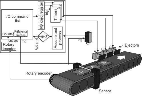
Again, an I/O command list is used to schedule the ejection of a part, and the rotary decoder output is used as the counter source of the I/O command list. A latch is used to store the command list's internal counter value upon the trigger signal from the sensor; the hooked function retrieves the counter value stored in the latch and adds it to a queue. When the grab is complete, some processing is performed and the part's type is determined. If the part is of type A, a command is added to discard the part 800 rotary encoder steps after the grab started; if the part is of type B, a command is added to discard the part 1000 rotary encoder steps after the grab started. If the part is of type C, a command is added to discard the part 1200 rotary encoder steps after the grab started. Since the rotary decoder output signal is the counter source, timers are again used. To specify the pulse duration in time (10 msec), an M_IMPULSE command is added to the command list to affect an I/O command register bit that triggers a timer that outputs a signal with an appropriate pulse.
// M_AUX_IO0 (output): Ejector A
// M_AUX_IO1 (output): Ejector B
// M_AUX_IO2 (output): Ejector C
// M_AUX_IO8 (input): sensor
// M_TIMER1: generate ejector pulse in time duration for ejector A
// M_TIMER2: generate ejector pulse in time duration for ejector B
// M_TIMER3: generate ejector pulse in time duration for ejector C
// M_AUX_IO14: Rotary encoder pin 1
// M_AUX_IO15: Rotary encoder pin 2
#define PULSE_WIDTH         10000000   // 10 ms
#define EJECTOR_OFFSET_A    800        // rotary decoder output counts to ejector A
#define EJECTOR_OFFSET_B    1000       // rotary decoder output counts to ejector B
#define EJECTOR_OFFSET_C    1200       // rotary decoder output counts to ejector C

static std::queue<MIL_INT64> ReferenceStamp;
static CRITICAL_SECTION FifoLock;
static MIL_ID CmdListId;
static MIL_ID SysId;
// ...
InitializeCriticalSection(&FifoLock); //Initalizes mutex

// Setup triggered grab.
MdigControl(MilDigitizer, M_GRAB_TRIGGER_SOURCE, M_AUX_IO0); //camera/digitizer aux I/O (input)
MdigControl(MilDigitizer, M_GRAB_TRIGGER_ACTIVATION, M_EDGE_RISING);
MdigControl(MilDigitizer, M_GRAB_TRIGGER_STATE, M_ENABLE);

// Setup rotary decoder; for simplicity, we assume the conveyor cannot move backward.
MsysControl(SysId, M_ROTARY_ENCODER_BIT0_SOURCE + M_ROTARY_ENCODER1, M_AUX_IO14);
MsysControl(SysId, M_ROTARY_ENCODER_BIT1_SOURCE + M_ROTARY_ENCODER1, M_AUX_IO15);
MsysControl(SysId, M_ROTARY_ENCODER_OUTPUT_MODE + M_ROTARY_ENCODER1, M_STEP_FORWARD);
MsysControl(SysId, M_ROTARY_ENCODER_STATE + M_ROTARY_ENCODER1, M_ENABLE);

// Setup Timer 1 for Ejector A
MsysControl(SysId, M_IO_SOURCE + M_AUX_IO0, M_TIMER1);
MsysControl(SysId, M_TIMER_TRIGGER_SOURCE + M_TIMER1, M_IO_COMMAND_LIST1 + M_IO_COMMAND_BIT0);
MsysControl(SysId, M_TIMER_DELAY + M_TIMER1, 0);
MsysControl(SysId, M_TIMER_DURATION + M_TIMER1, PULSE_WIDTH);

// Setup Timer 2 for Ejector B
MsysControl(SysId, M_IO_SOURCE + M_AUX_IO1, M_TIMER2);
MsysControl(SysId, M_TIMER_TRIGGER_SOURCE + M_TIMER2, M_IO_COMMAND_LIST1 + M_IO_COMMAND_BIT1);
MsysControl(SysId, M_TIMER_DELAY + M_TIMER2, 0);
MsysControl(SysId, M_TIMER_DURATION + M_TIMER2, PULSE_WIDTH);

// Setup Timer 3 for Ejector C
MsysControl(SysId, M_IO_SOURCE + M_AUX_IO2, M_TIMER3);
MsysControl(SysId, M_TIMER_TRIGGER_SOURCE + M_TIMER3, M_IO_COMMAND_LIST1 + M_IO_COMMAND_BIT2);
MsysControl(SysId, M_TIMER_DELAY + M_TIMER3, 0);
MsysControl(SysId, M_TIMER_DURATION + M_TIMER3, PULSE_WIDTH);

// Start all three timers at the same time
MsysControl(SysId, M_TIMER_STATE + M_TIMER1, M_ENABLE);
MsysControl(SysId, M_TIMER_STATE + M_TIMER2, M_ENABLE);
MsysControl(SysId, M_TIMER_STATE + M_TIMER3, M_ENABLE);

// Allocate a command list where commands are scheduled based on rotary decoder 1's output signal.
MsysIoAlloc(SysId, M_IO_COMMAND_LIST1, M_IO_COMMAND_LIST, M_ROTARY_ENCODER1, &CmdListId);
if (CmdListId != M_NULL)
{
   // Latch counter upon detection of part
   MsysIoControl(CmdListId, M_REFERENCE_LATCH_TRIGGER_SOURCE + M_LATCH1, M_AUX_IO8);
   MsysIoControl(CmdListId, M_REFERENCE_LATCH_ACTIVATION + M_LATCH1, M_EDGE_RISING);
   MsysIoControl(CmdListId, M_REFERENCE_LATCH_STATE + M_LATCH1, M_ENABLE);

   // Hook a function to sensor's signal (M_AUX_IO8); hook-handler function reads and queues
   // latched value. See previous example for sample code.
   MsysControl(SysId, M_IO_INTERRUPT_ACTIVATION + M_AUX_IO8, M_EDGE_RISING);
   MsysHookFunction(SysId, M_IO_CHANGE, &IoHookFunction, M_NULL);
   MsysControl(SysId, M_IO_INTERRUPT_STATE + M_AUX_IO8, M_ENABLE);

   // Start the grabbing and processing.
   // The processing function is called each time a frame is grabbed.
   MdigProcess(MilDigitizer, MilGrabBufferList, MilGrabBufferListSize,
      M_START, M_DEFAULT, ProcessingFunction, M_NULL);

   // Print a message and wait for a key press before stopping the processing.
   MosPrintf(MIL_TEXT("Press <Enter> to stop. \n\n"));
   MosGetch();
   MdigProcess(MilDigitizer, MilGrabBufferList, MilGrabBufferListSize,
      M_STOP, M_DEFAULT, ProcessingFunction, M_NULL);
}
// ...
Where the function hooked to the I/O interrupt event (which queues the latch) is the same as the previous example and the processing function is:
//Each time a new frame is grabbed in a buffer, this function is called.
static MIL_INT MFTYPE ProcessingFunction(MIL_INT HookType, MIL_ID HookId, void* HookDataPtr)
{
   BOOL ObjectTypeA, ObjectTypeB, ObjectTypeC = FALSE;
   MIL_INT64 RefStamp;
   MIL_ID ModifiedBufferId;

   /* Retrieve the MIL_ID of the grabbed buffer. */
   MdigGetHookInfo(HookId, M_MODIFIED_BUFFER + M_BUFFER_ID, &ModifiedBufferId);

   /* Execute the processing  */
   // ... PUT YOUR PROCESSING FUNCTION HERE AND SET ObjectTypeA/B/C ACCORDINGLY

   // Reference latch FIFO should not be empty, but just in case.
   while (ReferenceStamp.empty())
      MosSleep(1);

   // Remove a latched value from the queue.
   EnterCriticalSection(&FifoLock);
   RefStamp = ReferenceStamp.front();
   ReferenceStamp.pop();
   LeaveCriticalSection(&FifoLock);

   // ObjectTypeA/B/C are boolean values that are set by the processing section of the code
   if (ObjectTypeA)
      MsysIoCommandRegister(CmdListId, M_IMPULSE, RefStamp,
         EJECTOR_OFFSET_A, M_DEFAULT, M_IO_COMMAND_BIT0, M_NULL);
   else if (ObjectTypeB)
      MsysIoCommandRegister(CmdListId, M_IMPULSE, RefStamp,
         EJECTOR_OFFSET_B, M_DEFAULT, M_IO_COMMAND_BIT1, M_NULL);
   else if (ObjectTypeC)
      MsysIoCommandRegister(CmdListId, M_IMPULSE, RefStamp,
         EJECTOR_OFFSET_C, M_DEFAULT, M_IO_COMMAND_BIT2, M_NULL);

   return 0;
}
Parts traveling along a conveyor belt that are not fixed in position example
In this example, parts are moving along a conveyor belt, shifting in position as they move along after they are grabbed, but not moving ahead of any other part on the conveyor. The parts take a variable number of steps before reaching the ejector, which will discard the part if processing fails. Two sensors are placed along the conveyor belt. Sensor A is placed where the part is completely in the camera's field of view; while, sensor B is placed near the ejector such that when the part is no longer detected, it is completely in front of the ejector. The ejector requires a pulse of 10 msec (0.01 sec) to successfully discard a part.

As in the previous examples, an I/O command list (I/O command list B) is used to schedule the ejection of a part; in this case, the signal from sensor B is used as the counter source of the I/O command list so that commands can be scheduled based on the number of parts that have passed sensor B. Another I/O command list (I/O command list A) is used to get a count of the number of parts that have triggered sensor A when a new part is detected; in this case, the signal from sensor A is used as both the counter source and the trigger that latches the internal counter's value. The grab is triggered and a hooked function is called each time there is a trigger signal from sensor A. The hooked function retrieves and queues the number of parts that have passed by sensor A (by inquiring the latched value of I/O command list A) and the number of parts that have passed by sensor B (by inquiring the latched value of I/O command list B) at this moment. When the grab is complete, some processing is performed and a decision is made to discard or keep the part. If the part must be discarded, a command is added to I/O command list B to discard the part after the number of parts between sensor A and sensor B have passed by sensor B since the part in question was grabbed. Since the signal from sensor B is the counter source of I/O command list B but the duration of the ejector pulse must be specified in time (10 msec), an M_IMPULSE command is added to the command list to affect an I/O command register bit that triggers a timer that outputs a signal with an appropriate pulse.
// I/O assignment information:
// M_AUX_IO0 (output): Sent to ejector from timer 1
// M_AUX_IO8 (input): Sensor A
// M_AUX_IO9 (input): Sensor B
// M_TIMER1: generate ejector pulse in time duration
#define PULSE_WIDTH         10000000   // 10 ms

static CRITICAL_SECTION FifoLock;
static std::queue<MIL_INT64> SensorAQueue;
static std::queue<MIL_INT64> SensorBQueue;
static MIL_ID CmdListIdA, CmdListIdB;
static MIL_ID SysId;
// ...
InitializeCriticalSection(&FifoLock); //Initalizes mutex

// Setup triggered grab.
MdigControl(MilDigitizer, M_GRAB_TRIGGER_SOURCE, M_AUX_IO0); // camera/digitizer aux I/O (input)
MdigControl(MilDigitizer, M_GRAB_TRIGGER_ACTIVATION, M_EDGE_RISING);
MdigControl(MilDigitizer, M_GRAB_TRIGGER_STATE, M_ENABLE);

//Setup ejector pulse. M_IO_COMMAND_LIST2 is I/O command list B.
MsysControl(SysId, M_IO_SOURCE + M_AUX_IO0, M_TIMER1);
MsysControl(SysId, M_TIMER_TRIGGER_SOURCE + M_TIMER1, M_IO_COMMAND_LIST2 + M_IO_COMMAND_BIT0);
MsysControl(SysId, M_TIMER_TRIGGER_ACTIVATION + M_TIMER1, M_EDGE_RISING);
MsysControl(SysId, M_TIMER_DELAY + M_TIMER1, 0);
MsysControl(SysId, M_TIMER_DURATION + M_TIMER1, PULSE_WIDTH); // 10 msec
MsysControl(SysId, M_TIMER_STATE + M_TIMER1, M_ENABLE);

// Allocate the first command list (I/O command list A) based on sensor A (M_AUX_IO8)
MsysIoAlloc(SysId, M_IO_COMMAND_LIST1, M_IO_COMMAND_LIST, M_AUX_IO8, &CmdListIdA);
// Allocate the second command list (I/O command list B) based on sensor B (M_AUX_IO9)
MsysIoAlloc(SysId, M_IO_COMMAND_LIST2, M_IO_COMMAND_LIST, M_AUX_IO9, &CmdListIdB);
if (CmdListIdB != M_NULL)
{
   // Latch the counter value of I/O command list A and B upon detection of a part at sensor A.
   // This corresponds to the total number of parts that have passed sensor A.
   MsysIoControl(CmdListIdA, M_REFERENCE_LATCH_TRIGGER_SOURCE + M_LATCH1, M_AUX_IO8);
   MsysIoControl(CmdListIdA, M_REFERENCE_LATCH_ACTIVATION + M_LATCH1, M_EDGE_RISING);
   MsysIoControl(CmdListIdA, M_REFERENCE_LATCH_STATE + M_LATCH1, M_ENABLE);

   // This corresponds to the number of parts that have passed
   // sensor B the moment sensor A detects a new part.
   MsysIoControl(CmdListIdB, M_REFERENCE_LATCH_TRIGGER_SOURCE + M_LATCH1, M_AUX_IO8);
   MsysIoControl(CmdListIdB, M_REFERENCE_LATCH_ACTIVATION + M_LATCH1, M_EDGE_RISING);
   MsysIoControl(CmdListIdB, M_REFERENCE_LATCH_STATE + M_LATCH1, M_ENABLE);

   // Hook a function to sensor A's signal (M_AUX_IO8);
   // hook-handler function reads and queues latched value of each I/O command list.
   MsysControl(SysId, M_IO_INTERRUPT_ACTIVATION + M_AUX_IO8, M_EDGE_RISING);
   MsysHookFunction(SysId, M_IO_CHANGE, IoHookFunction, M_NULL);
   MsysControl(SysId, M_IO_INTERRUPT_STATE + M_AUX_IO8, M_ENABLE);

   // Start the grabbing and processing.
   // The processing function is called with each time a frame is grabbed.
   MdigProcess(MilDigitizer, MilGrabBufferList, MilGrabBufferListSize,
      M_START, M_DEFAULT, ProcessingFunction, M_NULL);

   // Print a message and wait for a key press before stopping the processing.
   MosPrintf(MIL_TEXT("Press <Enter> to stop. \n\n"));
   MosGetch();
   MdigProcess(MilDigitizer, MilGrabBufferList, MilGrabBufferListSize,
      M_STOP, M_DEFAULT, ProcessingFunction, M_NULL);
}
// ...
Where the function hooked to the I/O interrupt event and the processing function are:
// IO interrupt hook function to read and queue latched values of I/O command list A and B so that
// the two values can be used to schedule a command for the newly grabbed part if necessary.
static MIL_INT MFTYPE IoHookFunction(MIL_INT HookType, MIL_ID EventId, void *UserDataPtr)
{
   MIL_INT PinNb = 0;
   MIL_INT64 NumberOfSensorAObjects;
   MIL_INT64 NumberOfSensorBObjects;

   // If the signal that called the hooked function is M_AUX_IO8.
   MsysGetHookInfo(SysId, EventId, M_IO_INTERRUPT_SOURCE, &PinNb);
   if (PinNb == M_AUX_IO8)
   {

      // Get and queue latched value of I/O command list A.
      // This is the total number of parts that have passed sensor A.
      MsysGetHookInfo(SysId, EventId,
         M_REFERENCE_LATCH_VALUE + M_IO_COMMAND_LIST1 + M_LATCH1, &NumberOfSensorAObjects);
      // Get and queue latched value of I/O command list B.
      // This is the number of parts that have passed sensor B when a new part passes sensor A
      MsysGetHookInfo(SysId, EventId,
         M_REFERENCE_LATCH_VALUE + M_IO_COMMAND_LIST2 + M_LATCH1, &NumberOfSensorBObjects);
      EnterCriticalSection(&FifoLock);
      SensorAQueue.push(NumberOfSensorAObjects);
      SensorBQueue.push(NumberOfSensorBObjects);
      LeaveCriticalSection(&FifoLock);
   }

   return M_NULL;
}

//Each time a new frame is grabbed in a buffer, this function is called.
static MIL_INT MFTYPE ProcessingFunction(MIL_INT HookType, MIL_ID HookId, void* HookDataPtr)
{
   BOOL ShouldRejectTheObject = FALSE;
   MIL_INT64 NumberOfSensorAObjects;
   MIL_INT64 NumberOfSensorBObjects;
   MIL_INT64 NumberOfObjectsBetweenSensors;
   MIL_ID ModifiedBufferId;

   /* Retrieve the MIL_ID of the grabbed buffer. */
   MdigGetHookInfo(HookId, M_MODIFIED_BUFFER + M_BUFFER_ID, &ModifiedBufferId);

   /* Execute the processing  */
   // ... PUT YOUR PROCESSING FUNCTION HERE AND SET ShouldRejectTheObject ACCORDINGLY

   // Reference latch FIFO should not be empty, but just in case.
   while (SensorAQueue.empty() || SensorBQueue.empty())
      MosSleep(1);

   // Remove a latched value from the queue even if not ejecting.
   EnterCriticalSection(&FifoLock);
   NumberOfSensorAObjects = SensorAQueue.front();
   SensorAQueue.pop();
   NumberOfSensorBObjects = SensorBQueue.front();
   SensorBQueue.pop();
   LeaveCriticalSection(&FifoLock);

   // If required, insert an ejection pulse after the proper number of parts have passed sensor B.
   if (ShouldRejectTheObject)
   {
      // Establish number of parts between sensors A and B at the moment when the part was first grabbed.
      NumberOfObjectsBetweenSensors = NumberOfSensorAObjects - NumberOfSensorBObjects;
      // Insert ejection pulse after number of parts between the sensors have passed sensor B.
      MsysIoCommandRegister(CmdListIdB, M_IMPULSE, NumberOfSensorBObjects,
         (MIL_DOUBLE)NumberOfObjectsBetweenSensors, M_DEFAULT, M_IO_COMMAND_BIT0, M_NULL);
   }


   return 0;
}