Fast Fourier Transform
- See also

 Availability
 Previous
- Next

-
Perform a forward FFT (M_FORWARD), calculating the magnitude (M_MAGNITUDE) of the image. Scale the image within a displayable range using M_LOG_SCALE (this applies the formula, clog[1+|F(u,v)|]).
-
Find the frequency components representing the noise and design a mask image to remove these components. To design the mask image, clear the mask to a non-zero value, and then set the unwanted frequencies to 0, or vice versa.
-
Perform a simple FFT to obtain the real and imaginary components of the image, this time without calculating the magnitude.
-
Perform an MbufCopyCond() operation or an MbufClearCond() operation on both the imaginary and real parts of the image, with the mask as the condition buffer. This will remove the unwanted frequencies.
-
Finally, perform a reverse transform to obtain a filtered image.
A Fast Fourier Transform (FFT) is used to identify any consistent spatial patterns (of frequency) in an image (which can be caused, for example, by systematic noise). You can perform one or two dimensional FFTs using MimTransform(). For 1D transforms, each row or column is treated as a 1D signal. This type of transform separates a one dimensional signal into a set of sine and cosine waves of different frequencies. For a two-dimensional signal (image), it can be interpreted as the decomposition of an image into a set of 2D patterns. The composition of these waves make up the original waveform.
The forward Fourier transform is defined as:
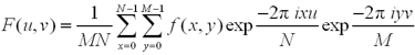
Where u and v are coordinates in the frequency domain and x and y are coordinates in the spatial domain. A forward FFT yields a real (R) and an imaginary (I) component of the image in a frequency domain (spectrum).
The reverse Fourier transform is defined as:
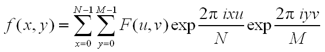
where x and y are the coordinates in the spatial domain and u and v are coordinates in the frequency domain.
Magnitude and phase
For a more visual understanding of the FFT results, you can calculate the phase and magnitude, using the MimTransform() function with M_MAGNITUDE. The magnitude is calculated as:

where R and I are the real and imaginary components of the image, respectively.
The following figures show single-frequency images and their centered magnitude. Since single-frequency images contain only one spatial frequency component, their corresponding frequency images appear as a single point of brightness with their associated negative-frequency mirrors. Note that the points in the frequency domain appear in the direction of the pattern. The distance between the points and the DC component represents the frequency of the pattern. The DC component appears at the center of the image when M_CENTER is used.
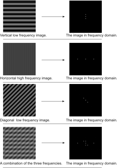
The spatial shift of each pattern in the image, in degrees, is called the phase. It is calculated using the formula atan(I/R). You can obtain the phase using the M_PHASE setting.
Typically, as is the case in the previous example, M_CENTER is used to center the real and imaginary components of the image in the frequency domain by repositioning their respective buffers' quadrants. The DC component is positioned at (SizeX/2-1, SizeY/2-1), where SizeX and SizeY are the width and height of the source buffer, respectively. If M_CENTER is not specified, the DC component appears in the upper left corner of the image. The following example illustrates the repositioning of a buffer's quadrants when M_CENTER is specified:

Filtering an image
To filter constant spatial patterns using FFTs:
If you know the frequency of the noise pattern and have designed the mask, you need only perform steps 3 to 5.
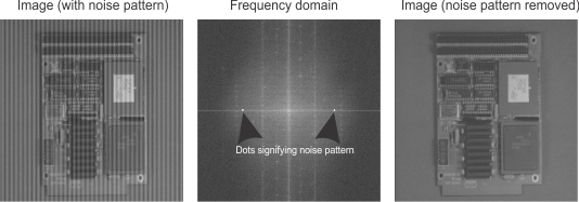
The following example performs an FFT on an image with a vertical noise pattern. A forward transform is performed to obtain the real and imaginary components of the image. The values of locations corresponding to the noise pattern are set to 0. Finally, a reverse transform is performed to obtain a spatial image without the noise pattern.