Child buffers, regions of interest, and fixturing
- See also

 Availability
 Previous
- Next

When working in MIL, you can operate on a specified subset of data of an image buffer. This can be done with child buffers or with regions of interest (ROI). You can also fixture the relative coordinate system of an image to the same point on an object, regardless of the location of the object in the image, so that you can position a region of interest or a module's search region according to an object's found location. This can be used, for example, when automating a series of measurement operations.
MIL-Lite does not support fixturing.
Child buffers
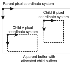
A child buffer is a specified subset of a data buffer (known as the parent buffer), associated with a MIL identifier. Child buffers occupy a specific rectangular area of the parent buffer. Since this area is part of the same physical memory space as the parent buffer, changes made to the data of the child buffer affect the data of the parent buffer and vice versa. Since a child buffer has a MIL identifier, it is considered a data buffer, and it can be used in the same context as its parent buffer; for example, it can be selected to a MIL display and be the only data that is displayed. A child buffer takes on the same attributes and type as its parent buffer. However, any pixel coordinates specified or returned when using a child buffer are relative to the child buffer's top-left corner.
Just as its parent buffer, a child buffer must be allocated so that it can be associated with an identifier and recognized as an entity by MIL. You can use one of the MIL functions from the table below to allocate the child buffer.
|
MIL function |
Monochrome parent buffer. |
Multi-band parent buffer. |
|
1D region of first row of band. |
1D region of first row of all bands. |
|
|
2D region of band. |
2D region of all bands. |
|
|
- |
Entire area of band chosen. |
|
|
- |
2D region of band chosen or 2D region of all bands. |
Specify a child buffer's size and offset keeping in mind the parent buffer's dimensions. Note that, as a subset of the parent buffer, a child buffer cannot exceed the bounds of its parent in any dimension. For example, a color child buffer cannot be created from a monochrome parent buffer.
Once you have finished using a child buffer, you must free it using MbufFree(), before freeing its parent buffer.
For more information, see the Child buffers subsection of the Using child buffers, ROIs, or a copy to manipulate specific data areas section of Chapter 21: Data buffers.
Regions of interest
A region of interest (ROI) is similar to a child buffer in that it identifies a subset of data in an image buffer. The ROI of an image buffer can be of any shape and can be composed of several non-contiguous areas. When dealing with processing operations that respect the ROI, all pixels outside the ROI are ignored. You can have the ROI move within the image buffer according to the relative coordinate system, if the image is calibrated. Note that, unlike a child buffer, an ROI does not have its own MIL identifier and cannot have results returned with respect to it.
Use MbufSetRegion() to create an ROI from an image mask or from the graphics in a 2D graphics list.
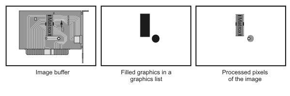
When defined from an image mask, the region of interest consists of the pixels corresponding to the non-zero pixels in the image mask. When defined from the graphics contained in a 2D graphics list, only areas corresponding to the graphics are processed. If the graphics defining the ROI are not filled, the ROI will consist of only the graphics' outline, which is one pixel thick. However, if the combination constant M_FILL_REGION is specified when calling MbufSetRegion(), the ROI will consider non-filled graphics as being filled. This is useful if you want to display the 2D graphics list defining the region of interest, or modify it interactively,without obstructing the target image.

It is not possible to set an ROI in an image buffer that has one or more child buffers. However, it is possible to define an ROI directly in a child buffer. The child buffer's ROI is not accessible from the parent buffer.
For more information, see the Specifying a region of interest subsection of the Using child buffers, ROIs, or a copy to manipulate specific data areas section of Chapter 21: Data buffers.
Fixturing an object with the relative coordinate system
A technique known as fixturing is available to place the relative coordinate system at a fixed position from an object. This is useful if the object could appear any number of times at any location or orientation in your images, and you want to apply the same measurement or inspection process to every instance of the object. Since fixturing is based on the relative coordinate system, your images must be calibrated even if they only use a one-to-one uniform camera calibration.
To fixture an object, you must first set up an analysis operation that will return the location(s) of the object in your image (for example, using Model Finder). Once you have established the location (reference location) for each instance of the object, create a loop that calls McalFixture() with M_MOVE_RELATIVE and the reference location of one of the instances. For each instance of your object, the relative coordinate system is placed at the reference location. In the loop, after displacing the relative coordinate system, set up the rest of the inspection process with respect to the relative coordinate system. You can now process each instance of your object, and have results returned with respect to the displaced relative coordinate system.
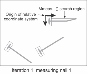
The following animation depicts a set of nails where the relative coordinate system is fixtured to each instance of the nail, before placing the MIL Measurement module's search region with respect to the relative coordinate system and then performing the analysis.

The following code snippet illustrates how to setup fixturing. An image calibrated with a uniform one-to-one camera calibration is used.
// [...]
// Associates the default uniform calibration context with your image;
// this sets the absolute coordinate system to have the same origin
// and orientation as the pixel coordinate system
// and sets the world units equal to 1 pixel.
McalUniform(TargetImage, 0.0, 0.0, 1.0, 1.0, 0.0, M_DEFAULT);

// Find all occurrences of the model in the target image.
MmodFind(ModCtx, TargetImage, ModRes);

// Allocate a stripe marker.
MIL_ID MeasStripe = MmeasAllocMarker(System, M_STRIPE, M_DEFAULT, M_NULL);
MmeasSetMarker(MeasStripe, M_ORIENTATION, M_HORIZONTAL, M_NULL);

// Use a graphics list to define the region to be fixtured and used by measurement.
const MIL_DOUBLE SearchRegionOriginX  = 30;
const MIL_DOUBLE SearchRegionOriginY  = 10;
const MIL_DOUBLE SearchRegionSizeX    = 200;
const MIL_DOUBLE SearchRegionSizeY    = 70;

MgraControl(M_DEFAULT, M_INPUT_UNITS, M_WORLD);
MgraRect(M_DEFAULT, GraphicLst, SearchRegionOriginX, SearchRegionOriginY,
                                SearchRegionSizeX, SearchRegionSizeY);
MbufSetRegion(TargetImage, GraphicLst, M_DEFAULT, M_NO_RASTERIZE + M_FILL_REGION, M_DEFAULT);

// [...]

MIL_INT NbFound = 0;
MmodGetResult(ModRes, M_GENERAL, M_NUMBER + M_TYPE_MIL_INT, &NbFound);

// For each found occurrence of the model.
for(MIL_INT i = 0; i < NbFound; i++)
   {
   // [...]

   // Moves the image's relative coordinate system to the reference position and
   // orientation of the current model occurrence.
   McalFixture(TargetImage, M_NULL, M_MOVE_RELATIVE, M_RESULT_MOD, ModRes, i,
                                    M_DEFAULT, M_DEFAULT, M_DEFAULT);

   // Measure the stripe in the fixtured search region.
   MmeasFindMarker(M_DEFAULT, TargetImage, MeasStripe, M_DEFAULT);

   // Analyze the results of the measured stripe.
   MmeasGetResult(MeasStripe, M_ANGLE + M_EDGE_FIRST  , &Edge1AngleDeg, M_NULL);
   MmeasGetResult(MeasStripe, M_ANGLE + M_EDGE_SECOND , &Edge2AngleDeg, M_NULL);

   // [...]
   }
For more information, see the Fixturing in MIL section of Chapter 27: Fixturing in MIL.