Generating a grid for calibration
- See also

 Availability
 Previous
- Next

-
Be consistent with your world units. All dimensions specified in world units must be in the same units. For example, if you specify your grid size in millimeters, you must specify your camera's field of view in millimeters.
In addition, for a fiducial grid, you must specify the world unit that you are using. In the example above, you must specify millimeters as your unit of measurement. Note that your unit of measurement is not checked in any way. What is encoded in the Data Matrix code is only the name that you give to your unit of measurement. There is no explicit or implicit unit conversions.
The following is a list of the available world units:
-
Metric units.
-
Imperial units.
-
Miscellaneous.
-
-
Set the grid's X- and Y-size to the required dimensions, in world units. For maximum calibration accuracy, your grid's size should encompass the entire field of view of all cameras, or the size should be at least as large as the working area of all cameras.
-
To automatically determine the number of rows and columns and the size of the squares/rectangles in the grid, you must set the size of the field of view and the resolution of the cameras. When automatically determined, the number and size of rows and columns will be set to maximize the total number of calibration points, while maintaining pixel and size restrictions for the chessboard squares/rectangles.
Set the camera's field of view by specifying the length of the X-axis in world units.
Set the camera's resolution by specifying the length of the X-axis in pixels.
If you have more than one camera, calculate the ratio of each camera's field of view/ resolution. Specify the field of view and resolution of the camera with the highest ratio.
Note that the values you specify for the field of view and resolution are used to heuristically determine the number of rows/column. When a camera has perspective distortion, you might have to increase the MIN_CAMERA_PIXELS_PER_SQUARE constant to compensate for chessboard rows or columns that are too small.
-
To manually specify the number of rows and columns, you must first disable the automatic determination of rows and columns, and then enter the number of required rows and columns. The size of the chessboard squares/rectangles are automatically determined.
Note that unless the ratio of rows and columns equals the ratio of the X and Y dimensions of the grid, it is possible that either the number of rows or the number of columns in your grid will be slightly lower than the specified number. The dimensions of the grid takes precedence over the number of rows or columns.
-
Specify a calibration point on the grid as the reference calibration point.
The reference calibration point is the calibration point typically used as the origin of the absolute coordinate system. By default, the reference calibration point is the calibration point closest to the center of the grid. When specifying a non-default position, you must provide explicit coordinates for the reference calibration point. The X-coordinate is the number of calibration points between the left-most column of calibration points and the required reference calibration point. The Y-coordinate is the number of calibration points between the top-most row of calibration points and the required reference calibration point. This implies that to specify the top-left calibration point as the reference calibration point, you must specify (0, 0) for the X- and Y-coordinates. In the following image, to specify the illustrated reference calibration point, you must specify 7 as the X-coordinate and 3 as the Y-coordinate.

-
Specify the number of fiducials that you need for your grid.
For most setups, a fiducial grid with a single fiducial is ideal. For setups where you have multiple cameras that cannot all see the entire grid, you might need to create multiple fiducials at strategic places on the grid so that each camera sees at least one fiducial on the grid.
Note that each Data Matrix code encodes the same grid information and the offsets that correspond to the same reference calibration point. If a camera sees more than one fiducial, only one is read because they each have the necessary information to set up the same absolute coordinate system.
-
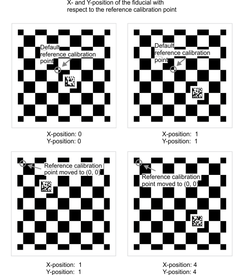
Specify the position of your fiducial(s) in the grid.
The position of the fiducial in your grid is specified as an X-and Y-coordinate, with respect to the current position of the reference calibration point. The X- and Y-coordinate is applied to the calibration point to the top-left of the Data Matrix code. When the coordinates of the fiducial are (0, 0), as illustrated in the top-left image below, a 2x2 Data Matrix code is placed over the calibration point to the bottom-right of the reference calibration point.
Add 1 to the X-coordinate to move the Data Matrix code right 1 calibration point and subtract 1 to move it left. Add 1 to the Y-coordinate to move it down 1 calibration point and subtract 1 to move it up. In the top-right image below, the fiducial is placed at (1, 1) from the unchanged default reference calibration point.
If you move the reference calibration point, for instance to the top-left calibration point, as in the image to the bottom-left, but keep the X- and Y-position of the fiducial (the position of the fiducial is [1, 1] in this example), the position of the fiducial on the grid will follow the new reference calibration point.
To keep the fiducial in place on the grid and change the reference calibration point, as in the image below-right, you must specify a new position for the fiducial that considers the new position of the reference calibration point.
Note that the fiducial must not be too close to the edge of the grid. The fiducial zone of your fiducial must be at least 1.5 squares away from the edge of the grid.
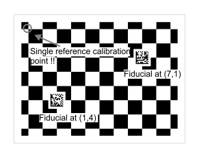
When specifying more than one fiducial, you must specify each fiducial's position with respect to the same reference calibration point, as in the image below.
-
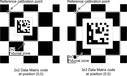
For each fiducial, specify whether you need a 2x2 fiducial zone or a 3x3 fiducial zone; this affects the size of the fiducial.
Typically, use a 2x2 fiducial zone. The 3x3 fiducial zone is usually used when the resolution of the camera produces a Data Matrix code that is too small to read. To read a Data Matrix code, the pixel size of the individual cells of the code in your image must be at least 3 pixels wide. If you have a low resolution camera or if the generated Data Matrix code has many cells, the cells might be too small to read. In this case, specify to create a larger Data Matrix code that takes up 9 grid squares/rectangles (3x3) instead of the typical 4 grid squares/rectangles (2x2). This produces a larger fiducial zone, as in the following image. The maximum size for a fiducial zone is 3x3.
Note that the additional size of the fiducial covers up more calibration points, which lowers the total number of calibration points used for calibration. This can lower the overall accuracy of the calibration, especially when calibrating in M_LINEAR_INTERPOLATION mode.
-
Configure gridconfig.h and run the CalGenChessGrid.cpp example.
-
Specify that you will manually set the number of rows and columns. By default, the number of rows and columns are automatically established.
-
Specify the exact dimensions of your existing chessboard grid. To ensure this, set the exact length and width of your existing chessboard grid and the exact number of rows and columns it has.
-
Specify the grid's reference calibration point, the number of fiducials, and their positions, according to your requirements.
-
-
Print the fiducial(s). The individual images of the fiducial(s) are in the same folder as the image of the fiducial grid.
-
Print the fiducial as large as you can, given the constraints discussed below. This will make the Data Matrix code easier to read.
Use this image of a 2x2 fiducial zone code to understand how large you will be able to print the Data Matrix code. The space requirements are the same for the 3x3 fiducial zones.

-
The Data Matrix code must have a white zone at least 2 Data Matrix cells wide around it. If the white space is too thin, the Data Matrix code might not be read, resulting in a failed calibration. The fiducial(s) output by CalGenChessGrid.cpp already have sufficient white space. Do not crop the white space.
Note that while the image of the Data Matrix includes sufficient white space, if you print the code on white paper, you might not be able to see where the white space ends. When you cut out the fiducial, consider the necessary white space around the Data Matrix code.
-
The fiducial, including the white space, must have a cushion between it and the edge of the fiducial zone. The cushion must be at least 0.4 chessboard grid squares wide all around the fiducial. You might need to shrink your fiducial to meet this minimum.
-
The pixel size of the Data Matrix cells in your fiducial grid image must be at least 3 pixels wide. This is not a physical constraint of the printed fiducial, but if the image of your fiducial grid does not have enough resolution to satisfy this constraint and the constraints above, you might have to increase the size of the fiducial and place it in a larger fiducial zone. You can specify to create a larger Data Matrix code by configuring gridconfig.h before running the CalGenChessGrid.cpp example. This larger code is placed in a fiducial zone that has 9 grid squares/rectangles (3x3) instead of the typical 4 grid squares/rectangles (2x2).
-
-
Affix the fiducial(s) to your existing chessboard grid.
-
Place the fiducials on your existing grid in the exact spot and in the same orientation that they appear in the generated version of the fiducial grid.
The position and orientation of the fiducial is important. A Data Matrix code with no offset encodes the grid's reference calibration point to be the closest calibration point to the top-left corner of the Data Matrix code, considering its proper orientation. Illustrated on the left below is the original fiducial grid that the example generates. If the Data Matrix code from the example is printed and affixed to your existing chessboard grid at a different location than it was generated for, the reference calibration point moves, as in the image on the right.

Note that if you affix the Data Matrix code in a different position than was generated, you must still ensure that the fiducial zone is at least 1.5 grid squares away from the edge of the grid for both the 2x2 and 3x3 Data Matrix codes.
If the Data Matrix code is rotated, the grid's reference calibration point also changes, as does the orientation of the absolute coordinate system, as in the image below.

-
Pay close attention to position and orientation of each separate Data Matrix code when using a multi-fiducial grid.
Moving a single Data Matrix code is not necessarily a problem; it will simply move the resulting absolute coordinate system. If you have more than one fiducial and you place one of them incorrectly, they will each specify a different reference calibration point for the grid. This will not necessarily generate an error, but will result in unpredictable behavior. You cannot use the same Data Matrix code twice on the same grid.

If you need to affix more than one fiducial to your existing chessboard grid, you must use CalGenChessGrid.cpp to generate all the fiducials and you must place them in the exact spot that they appear in the generated fiducial grid image. The fiducials are numbered in the order specified in CalGenChessGrid.cpp.
-
MIL is distributed with grids that you can print and use: FiducialCalibrationGrid_Letter.pdf ChessboardCalibrationGrid_15x16_Letter.pdf, ChessboardCalibrationGrid_18x22_Letter.pdf, CircleCalibrationGrid_15x16_Letter.pdf, CircleCalibrationGrid_18x22_Letter.pdf. These files are located in the Matrox Imaging\Images directory. However, you might need to create a grid that better suits your setup. To generate a custom fiducial or chessboard grid of squares/rectangles, MIL provides an example, CalGenChessGrid, accessible from the Matrox Example Launcher.
Before running CalGenChessGrid.cpp to generate the required fiducial or chessboard grid, you must set constants in gridconfig.h, according to your grid requirements. Once you have set the constants, run the example to generate an image of the grid that you can then print.
Generating a grid using CalGenChessGrid
There are many values that you can configure before using CalGenChessGrid, but typically you will focus on two categories: the physical setup and the grid's fiducials. Keep in mind that a chessboard grid is simply a fiducial grid where the number of fiducials is set to 0.
Specifying the physical setup
When generating fiducial grids or chessboard grids, you must describe the physical setup in terms of the grid's dimensions, such as its size in world units, and the camera's attributes, such as its field of view. The following should be considered for your setup:
Specifying the grid's fiducials
The grid's fiducials are Data Matrix codes that encode the grid's physical information discussed above and also the position of the grid's reference calibration point. The fiducial grid, regardless of its total number of fiducials, has a single reference calibration point, which you must specify before running the example. The grid can have zero, one, or many fiducials. If you specify a grid with zero fiducials, this is equivalent to a chessboard grid.
The following fiducial settings should be considered for your setup:
Printing the grid
Once you have a calibration grid, either by generating it using the example or by choosing one of the grids provided with MIL, you must print the grid. The grid that the example produces is a png named ChessGrid.png and can be found in the \Documents\Matrox Imaging\MIL\Examples\Processing\2dCalibration\CalGenChessGrid\C++ folder.
An in-depth explanation of printing options is beyond the scope of this section. Typically, you must print the fiducial grid at as high a resolution as you can. It is recommended that your print resolution be at least 600 DPI. You should not attempt to scale or fit the image; the printer must print the fiducial grid exactly as is.
Whichever way you print the grids, you must physically measure the grid spacings afterward so they are accurate. The more accurate your physical grid is, the better the calibration and all subsequent MIL measurements will be. Consider that even a 0.1 mm deviation per grid square is 2% of a 5 mm row or column spacing. This can result in calibration imprecision.
Note that the fiducial grid that is distributed with MIL is encoded to have a row and column spacing of exactly 10 mm.
Adding printed fiducials to an existing chessboard grid
If you already have a highly accurate chessboard grid, you can still take advantage of calibrating your camera(s) with a fiducial grid, by affixing one or more valid Data Matrix codes to your existing grid. You must configure gridconfig.h and run the CalGenChessGrid.cpp example, print the Data Matrix codes the example outputs, and affix the printed codes to you existing chessboard grid at the exact spot where they should go, based on how you configured the example. The CalGenChessGrid.cpp example outputs two or more images, one image of the complete fiducial grid and one image for each fiducial in the fiducial grid.
Note that the fiducials do not need to be printed with the same level of accuracy as the grid squares/rectangles themselves because they are not used as calibration points; the Data Matrix code only needs to be accurate enough to be easily read.
To affix fiducials to an existing grid, perform the following: