How coordinates and non-positional results are transformed
- See also

 Availability
 Previous
- Next

If you have a calibrated image or camera calibration context, you can perform coordinate transformations and transform non-positional results from pixel units to world units (or vice versa).
Transforming from the pixel to a specified world coordinate system
If you have a pair of coordinates, or a list of coordinates, in the pixel coordinate system, you can determine their position in a specified world coordinate system. For a pair of coordinates, use McalTransformCoordinate() to perform the transformation. However, if you have a list of coordinates, use McalTransformCoordinateList() or McalTransformCoordinate3dList(), which have better performance than performing multiple calls to McalTransformCoordinate().
When transforming from pixel to world coordinate systems, McalTransformCoordinate(), McalTransformCoordinateList(), and McalTransformCoordinate3dList() trace a line (simulating a light ray) from the effective pinhole of the camera through the specified point in the image plane. Since all world points along a given light ray project onto the same point in the image plane, every world point along the ray is theoretically a solution. Therefore, to return a unique solution, the line is intersected with the XY-plane (Z=0) of the relative coordinate system, and then the point of intersection is transformed to the specified world coordinate system.
The following image depicts the typical case where the camera is placed above a setup. Since the relative coordinate system is parallel to the image plane, any point in the image can be transformed to its real-world equivalent.
Since coordinates are transformed with respect to the relative coordinate system, if the relative coordinate system is displaced between calls to McalTransformCoordinate(), McalTransformCoordinateList(), and McalTransformCoordinate3dList(), the returned positions will not necessarily be comparable.
If the image plane is not parallel to the relative coordinate system, due to the camera setup or a displacement of the relative coordinate system, not every point in the image plane will have a valid real-world equivalent. Therefore, three types of intersections can occur when transforming from the image plane to a world coordinate system. If the specified point in the image plane corresponds to a point in front of the camera in the relative coordinate system, that point in the relative coordinate system is transformed to the destination world coordinate system. However, if the line traced through the specified point in the image plane does not intersect the XY (Z=0) plane of the relative coordinate system, M_INVALID_POINT is returned. If the line's intersection with the XY-plane of the relative coordinate system is behind the camera, then the mathematically computed value is transformed to the destination world coordinate system, even though it is not the correct world location of the point.
However, using McalTransformCoordinate(), McalTransformCoordinateList(), or McalTransformCoordinate3dList() with M_NO_POINTS_BEHIND_CAMERA, returns M_INVALID_POINT if the computed point is behind the camera.
If you are certain that all specified pixel coordinates being transformed will be in the camera's field of view, do not use M_NO_POINTS_BEHIND_CAMERA, since it adds computation time to the transformation.
Note that, for the perspective based camera calibration mode, the effective pinhole of the camera is implicitly defined, so the conversion of coordinates is the same as explained above. Uniform and linear interpolation camera calibration modes do not model an effective pinhole, and instead use a linear and piecewise linear mapping to transform a pair of coordinates, respectively.
Transforming from the world to the pixel coordinate system
To convert a point specified in a world coordinate system to its corresponding point in the pixel coordinate system, McalTransformCoordinate(), McalTransformCoordinateList(), and McalTransformCoordinate3dList() transform the specified point to the relative coordinate system, and then form a line (simulating a light ray) from the point in the XY (Z=0) plane of the relative coordinate system to the effective pinhole of the camera. The functions then return the intersection of this line with the image plane.
The following image depicts the typical case where the camera is placed above a setup. Since the relative coordinate system is parallel to the image plane, any point in the world coordinate system can be transformed to its pixels equivalent.
If the relative coordinate system is not parallel to the image plane, due to the camera setup or a displacement of the relative coordinate system, not every point specified in a world coordinate system will have a valid pixel equivalent. Three types of intersections can occur when transforming from a world coordinate system to the image plane. If the point in the XY-plane of the relative coordinate system corresponds to a point in front of the camera, the intersection point in the image plane is returned. However, if the line formed through the specified point in the XY-plane of the relative coordinate system does not intersect the image plane, M_INVALID_POINT is returned since there is no intersection. If the point that forms the line from the XY-plane of the relative coordinate system is behind the camera, then the mathematically computed pixel value is returned, even though it does not correspond to the world location of the pixel in the image.
However, using McalTransformCoordinate(), McalTransformCoordinateList(), or McalTransformCoordinate3dList() with M_NO_POINTS_BEHIND_CAMERA, returns M_INVALID_POINT if the calculated point does not have a correct real-world equivalent.
If you are certain that all specified world points being transformed will be in the camera's field of view, do not use M_NO_POINTS_BEHIND_CAMERA, since it adds computation time to the transformation.
Note that, for the perspective based camera calibration mode, the effective pinhole of the camera is implicitly defined, so the conversion of coordinates is the same as explained above. Uniform and linear interpolation camera calibration modes, do not model an effective pinhole, and instead use a linear or piecewise linear mapping to transform a pair of coordinates, respectively.
Transforming from one world coordinate system to another
McalTransformCoordinate3dList() can be used to transform any specified list of points from a source world coordinate system to a destination world coordinate system. The returned position is the same physical point, but is expressed with respect to the target coordinate system.
The following image depicts two coordinate systems, where a specified point has been transformed from one coordinate system to another.
Generating unit vectors from the pixel coordinate system (or vice versa)
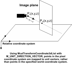
You can transform a list of coordinates from the pixel coordinate system to a series of unit vectors using McalTransformCoordinate3dList() with M_UNIT_DIRECTION_VECTOR. This generates unit vectors for each specified point in the image plane. The unit direction vector is generated by determining the direction vector between the effective pinhole of the camera and the point specified in the image plane. Since it is a unit vector, it has a magnitude of 1, and only gives the direction along which a world point could be found. Similarly, you can specify a unit direction vector and determine the corresponding point in the pixel coordinate system.
Transforming coordinates from a depth map to a world coordinate system (or vice versa)
You can use McalTransformCoordinate3dList() to transform any specified list of points from a source depth map to a destination world coordinate system. By specifying a point's pixel coordinates and intensity value, McalTransformCoordinate3dList() determines the location of the specified point in the target world coordinate system. Similarly, you can specify a point in the world coordinate system and determine its location and intensity in the depth map.
McalTransformCoordinate3dList() only transforms coordinates from a fully corrected depth map. For more information, see Chapter 40: 3D reconstruction using laser line profiling.
Using piecewise linear camera calibrations
When transforming coordinates from an image that has been calibrated using a piecewise linear camera calibration mode (allocated using McalAlloc() with M_LINEAR_INTERPOLATION), the transformation could be inaccurate if the coordinate being transformed is outside the calibrated area. The calibrated area is the space that was defined by the calibration points during calibration. Since an extrapolation is performed for points outside the calibration area, the accuracy of the transformation decreases. Using McalTransformCoordinate(), McalTransformCoordinateList(), or McalTransformCoordinate3dList() with M_NO_EXTRAPOLATED_POINTS, all points outside the calibration area will return M_INVALID_POINT.
Transforming Results
If you have a calibrated image or a camera calibration context, you can use McalTransformResult() to transform several different measures from pixel to world units (or vice versa).
You can transform an area specified in pixel units, and determine its value in world units, using McalTransformResult() with M_AREA. Similarly, you can convert a value in world units to its pixel unit equivalent. If you have a constant pixel size in X and Y, the transformation will be exact.
You can transform a length in the X or Y direction specified in the pixel coordinate system, and determine its real-world length, using McalTransformResult() with M_LENGTH_X or M_LENGTH_Y. Similarly, you can convert a real-world length to its pixel length. If you have a constant pixel size in X and Y, the transformation will be exact.
If you want to transform an arbitrary length that lies in any direction, use McalTransformResult() with M_LENGTH. If you have a constant pixel size in X and Y and no perspective distortion, such as a uniform camera calibration, the transformation will be exact. However, if you do not have an identical scaling in the X and Y directions, an approximation will be used to determine the best value to give the specified length in real-world units. If the difference between the X and Y scales is large, the approximation will be less accurate.
The following image shows the area and length results that can be transformed.
If you want to transform a specified angle at a particular position from the pixel coordinate system to the world coordinate system (or vice versa), you can use McalTransformResultAtPosition() with M_ANGLE. You must also specify the position at which you want to transform the angle.
The following is an image of a rail road track, which has significant perspective distortion. An angle measurement is taken between the horizontal and the tracks rail. The angle between the horizontal and the rail in the image is 55°, but after applying McalTransformResultAtPosition() with M_ANGLE, the actual angle of 90 degrees is returned.
If you do not have any positional information and you want to convert an angle from pixel units to world units, you can use McalTransformResult() with M_ANGLE. However, if you do not have a constant pixel size in both X and Y, McalTransformResult() will return an approximate value.