Verification process and grading your code
- See also

 Availability
 Previous
- Next

-
In the environment in which you will eventually be grading your codes, grab an image of a perfectly printed sample code using MdigGrab() (for example, an image of a code conformance test card for your code type, such as the GS1 Data Matrix calibrated conformance standard test card or the NIST-traceable EAN/UPC calibrated conformance test card).
-
Set the aperture of the code model to the recommended aperture for the code. Typically, you set McodeControl() with M_APERTURE_MODE to M_RELATIVE and M_RELATIVE_APERTURE_FACTOR to M_AUTO; see the Setting the aperture subsection of this section for more information on setting the aperture.
-
Call McodeGrade(). Then, retrieve the overall grade using McodeGetResult() with M_OVERALL_SYMBOL_GRADE.
-
If the resulting grade is not an A, then as necessary, adjust the image setup to:
-
Maximize the contrast and minimize noise in the image.
-
Avoid pixel saturation.
-
Have a cell size of at least 3. A smaller cell size results in a less robust result.
-
Have a uniform foreground and background grayscale level (that is, there should be no glare or dark spots present in the image).
-
-
Repeat steps 1-4 until the resulting grade is an "A" (or the best possible grade given the surface on which the code is printed).
-
For 1D code types, get the recommended aperture size, using McodeGetResult() with M_RECOMMENDED_APERTURE_SIZE.
Smooth the image using multiple calls to MimConvolve() with M_SMOOTH. MimConvolve() should be called at least once and at most a number of times equal to the following: (Recommended Aperture size + 0.5)/2
Find the minimum and maximum pixel values in the smoothed image using MimFindExtreme() with M_MIN_VALUE + M_MAX_VALUE. These values will be used as the minimum calibrated reflectance and the maximum calibrated reflectance, respectively.
-
For 2D code types, get the minimum and maximum reflectance (grayscale) values, using McodeGetResult() with M_R_MIN and M_R_MAX, respectively. These values will be used as the minimum calibrated reflectance and the maximum calibrated reflectance, respectively.
-
Set the minimum and maximum calibrated reflectance to the values previously determined in step 6 or 7, using McodeControl() with M_MINIMUM_CALIBRATED_REFLECTANCE and M_MAXIMUM_CALIBRATED_REFLECTANCE, respectively.
-
If the sample code and target code are of different code types, remove your sample code model from your code context and add a new code model for your target code type.
-
Grade your target codes. It is important not to modify the setup for the remainder of the grading process.
-
To retrieve the modulation of the code occurrence, as a grade calculated using the ISO standard, use M_MODULATION_GRADE.
-
To retrieve the modulation of the code occurrence calculated using the ISO/IEC TR 29158 standard, use M_CELL_MODULATION_GRADE.
-
To retrieve the modulation of each codeword as a grade, use M_CODEWORD_MODULATION_GRADE.
-
To retrieve the modulation of the start/stop patterns of 2D cross-row and composite code types, as a grade, use M_SCAN_MODULATION_GRADE.
-
To retrieve the reflectance margin grade of a code occurrence, use M_REFLECTANCE_MARGIN_GRADE.
-
To retrieve the minimum reflectance (grayscale value of the cell in the code occurrence), use M_MINIMUM_REFLECTANCE_GRADE.
-
To retrieve the reflectance margin of each codeword, use M_CODEWORD_REFLECTANCE_MARGIN_GRADE.
-
To retrieve the decodability grade of the entire code occurrence, use M_DECODABILITY_GRADE.
-
To retrieve the decodability grade of the scan reflectance profile, use M_SCAN_DECODABILITY_GRADE.
-
To retrieve the decodability grade for each codeword, use M_CODEWORD_DECODABILITY_GRADE.
-
To retrieve the decodability grade of the start/stop patterns of the code occurrence, use M_SCAN_DECODABILITY_GRADE.
-
Absolute aperture setting. To set your aperture size as a fixed value, use M_APERTURE_MODE set to M_ABSOLUTE.
-
MIL calculated aperture setting. To have MIL calculate the aperture size as a multiplicative factor of the cell size, use M_APERTURE_MODE set to M_RELATIVE.
-
Physically measure the entire code with a ruler. Note that this result must be in millimeters.
-
Read the code from a typical image of the code, using McodeRead().
-
Determine the length of the code in pixels. This can be done in three different ways:
-
For Data Matrix and QR codes, multiply the cell size (McodeGetResult() with M_CELL_SIZE) by the number of cells across the code, as defined by the specification for your code type.
For 1D codes, use McodeGetResult() with M_SIZE_X, making sure that M_RESULT_OUTPUT_UNITS is set to M_PIXEL if the image was calibrated.
-
Use the MIL Measurement module to set two point markers to identify the start and end of your code, using MmeasSetMarker() with M_POSITION. Then, calculate the distance between two markers using MmeasCalculate().
-
Use an interactive tool, such as the MIL Code Reader Interactive Utility.
-
-
Divide the measurement in millimeters by the length of the code in pixels.
-
Set M_PIXEL_SIZE_IN_MM to this result.
-
To perform the reflectance calibration phase:
-
Place an A-grade code, printed on a code conformance test card, in the field of view (for example, the GS1 Data Matrix calibrated conformance standard test card or the NIST-traceable EAN/UPC calibrated conformance test card); the code is used as the reference code. The reference code can be of any code type; it is not restricted to the Aztec, Data Matrix, QR, or Micro QR code type.
-
Allocate a code context and add a code model that has the same type as the reference code.
-
Set the aperture of the code model to the recommended aperture for the reference code. Typically, you set McodeControl() with M_APERTURE_MODE to M_RELATIVE and M_RELATIVE_APERTURE_FACTOR to M_AUTO; see the Setting the aperture subsection of this section for more information on setting the aperture.
-
Adjust the lighting according to the ISO/IEC TR 29158 standard.
-
Grab an image of the reference code, using MdigGrab().
-
Call McodeGrade().
-
Calculate the mean light ratio: ((McodeGetResult() with M_MEAN_LIGHT_CALIBRATION) / max possible grayscale of buffer).
-
If the mean light ratio is within 70% and 86%, the image of the reference code has an acceptable reflectance. If not, adjust your environmental factors (the location, camera, and/or lighting setup) and repeat steps e to g until the mean light ratio is acceptable.
-
Establish the System Response value (SRcal) for the reflectance calibration phase. The System Response value is a user-defined aggregate of environmental factors that you used to create the conditions for an acceptable code. For example, you could set the System Response value to be ( Exposure time * Gain factor).
-
-
To perform the target grading phase:
-
If the reference code (printed) and target code (DPM) are of different code types, allocate another code context and add a code model that has the same type as the target code.
-
Set the grading standard to ISO/IEC TR 29158 using McodeControl() with M_GRADING_STANDARD set to M_ISO_DPM_GRADING, which specifies the most recent version of ISO/IEC TR 29158. To use an earlier grading standard, use McodeControl() with M_GRADING_STANDARD_EDITION set to the required grading standard.
-
Load the reflectance and mean light values from the reflectance calibration phase into the code context of the target code. To do so with one call, use McodeControl() with M_DPM_CALIBRATION_RESULTS and the result buffer from the reflectance calibration phase. Alternatively, retrieve the reflectance and mean light values separately from this result buffer, and set the values into the code context of the target code using McodeControl() with M_REFLECTANCE_CALIBRATION and M_MEAN_LIGHT_CALIBRATION, respectively.
-
Set the System Response value derived from the reflectance calibration phase (SRcal) using McodeControl() with M_SYSTEM_RESPONSE_CALIBRATION.
-
Acquire an image of the target code, such that all environmental factors are initially the same as the reflectance calibration phase.
-
Set the System Response value for the target grading phase using McodeControl() with M_SYSTEM_RESPONSE_TARGET. To set the System Response value, use the same formula as the one used during the reflectance calibration phase, mentioned previously. For example, if you set the System Response value for the reflectance calibration phase to (Exposure time * Gain factor), set the System Response value for the target grading phase to (Exposure time * Gain factor).
-
Call McodeGrade().
-
Calculate the mean light ratio: ((McodeGetResult() with M_MEAN_LIGHT_TARGET) / max possible grayscale of buffer).
-
If the mean light ratio is within 70% and 86%, the image of the target code has an acceptable reflectance. If not, adjust only those environmental factors used to calculate the System Response value (for example, the exposure time and gain factor) and repeat steps e to h until the mean light ratio is acceptable. During the target grading phase, you should not alter any environmental factors other than those used to calculate the System Response value.
-
-
Grade your target codes using the code context from the target grading phase.
A code, once printed on a physical medium (such as a labeling sticker, a bag, or package), should be read and validated to ensure that there were no errors in the print process. This ensures that the code is readable by most types of imagers (such as, bar code scanners) that support your code type. For this purpose, the industry has created a set of standard print quality specifications (ISO standards). These standards can be used in two distinct phases: one to prepare the physical environment in which to best validate your code so that you test the printed code and not the setup in which it is read (such as lighting, code angle, quality of the code reader), and the other to validate the code that is being read.
You can use McodeGrade() for both phases. You can use it to help set up a code verification system according to the relevant ISO standards, as well as use it to grade the quality of printed codes. Depending on the code type and the attribute being tested, most tests are graded from 0.0 to 4.0 (F to A), or given a pass or fail mark. Use McodeGetResult() to retrieve these results.
Note that McodeGrade() is not supported for 4-state, Pharmacode, Postnet, and Planet 1D code types.
You can grade a single code occurrence or multiple code occurrences with each call to McodeGrade(), depending upon your requirements. In addition, by default McodeGrade() internally performs a read operation before performing the grading operation. However, to speed up the process, you can perform the read operation using McodeRead() and pass the code read result buffer to McodeGrade().
This section will guide you through the steps in using the MIL Code module to prepare your code setup for verification, as well as provide additional details for understanding the grading results from the MIL Code module.
Preparing your code setup for verification
Before you can validate the print quality of a code, you must configure your setup so that you are analyzing the printed code and not how well the code can be read in the current environment. The general ISO standards, ISO/IEC 15416 and ISO/IEC 15415, provide only general guidelines for configuring your setup for code verification. The following procedure is designed to assist in modifying your setup until ideal conditions are obtained. A grabbed image of a near-perfect code is used since you know the grade of a perfect code should be A, as long as the setup is not influencing the grade.
Note that for better accuracy, after adjusting your setup using an A-grade code, you can also grab and test images of non-perfect codes with known grades, if present on your code conformance test card. For these codes, instead of retrieving the overall grade in step 3, retrieve the grade obtained for the code attribute that is not perfect using McodeGetResult() with M_..._GRADE to see if the returned grade matches the known grade.
Attributes that can be graded
The following table lists the common code attributes that can be graded, including the attributes of the scan reflectance profiles, using MIL.
|
Attribute |
Notes |
|
|
Axial nonuniformity |

|
This attribute is a measure of how spacing between sampling points differs between the X- and Y-axis (width to height). |
|
Contrast |

|
This attribute is a measure of the contrast in the cells of the code occurrence or in the entire code occurrence. The higher the contrast, the better it is for scanning purposes and the better the grade. |
|
Decode |
|
This attribute is a measure of the success or failure of the decoding algorithm and is used to determine if the code is readable. |
|
Defects |

|
This attribute is a measure of the defects, or local deviations, in the scan reflectance profiles of the code. |
|
Fixed-pattern damage |

|
This attribute is used to grade the damage relating to the finder pattern and/or clock pattern of a 2D Data Matrix code. |
|
Grid nonuniformity |

|
This attribute is calculated as the amount of deviation of the code occurrence's actual grid from an ideal grid. |
|
Minimum edge contrast |

|
This attribute is calculated as the contrast between two adjacent regions (for example, a bar and an adjacent space). |
|
Print growth |
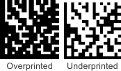
|
This attribute is a measure of the extent in which the boundaries of the black and white markings of the code occurrence are within their cell's boundaries. |
|
Start/stop pattern |

|
This attribute is used to grade the quality of the pattern that marks the end points of the code occurrence. |
|
Unused Error Correction |

|
This is a measure of the extent in which regional or spot damage in the code occurrence has eroded the reading safety margin that error correction provides. |
Note that an overall symbol grade can also be returned, using McodeGetResult() with M_OVERALL_SYMBOL_GRADE. For 2D codes, this is a measure of the worst grade for the results of a specific code occurrence. For 1D codes, it is a measure of the average grade for the results of a specific code occurrence.
Other code attributes can also be evaluated with the grading operation, but they return a value as opposed to a grade.
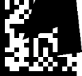
Understanding fixed pattern damage
The fixed pattern (also known as the fixed orientation pattern and the finder pattern) of a printed code (symbol) enables scanning equipment to identify and locate the code. Damage in the finder pattern of a code can make it unreadable. McodeGrade() can establish a grade for multiple aspects of the fixed pattern of a code occurrence in an image.
|
Code type (and encoding scheme if applicable) |
Fixed pattern |
Available results |
|
M_AZTEC code type with M_ENC_AZTEC_COMPACT |

Has a 2-ring bull's eye (A segment), whereby each corner of the center bull's eye uses a different, fixed orientation pattern for determining symbol orientation. |
|
|
M_AZTEC code type with M_ENC_AZTEC_FULL_RANGE |

Has a 3-ring bull's eye (A segment), whereby each corner of the center bull's eye uses a different, fixed orientation pattern for determining symbol orientation. In addition, it has a fixed reference grid along every 16th row and column (B segments) to help map the data layers. |
|
|
M_DATAMATRIX code type |

Has L1, L2, QZL1, and QZL2 segments. In addition, it has clock track and solid (clock pattern and adjacent solid area) segments. |
|
|
M_QRCODE code type |

Has A1, A2, A3, B1, B2, and C segments. |
|
|
M_MICROQRCODE code type |

Has A1, B1, and B2 segments. |
Understanding modulation versus reflectance margin with 2D codes
To analyze whether a given cell is considered part of the foreground or the background, you can grade its modulation and/or reflectance margin. Both modulation and reflectance margin rely on your code occurrence's threshold. When reading a 2D code occurrence, if the grayscale value of a cell (also called its reflectance value) is above the threshold value, it is considered light. Values close to the threshold are considered ambiguous, while values further away are considered unambiguous. For example, consider a given 2D matrix code occurrence that has a symbol contrast of 255 and a computed threshold of 128. In this case, if a cell has a grayscale value of 255, it is a light cell. This is considered unambiguous since 255 is very far from 128. If a cell's grayscale value is 132, however, the cell is still considered light (since it is over the computed threshold), but the difference between the grayscale value of the cell and the threshold is low enough that the result is considered ambiguous by most grading specifications. In the following image, the circled cells are examples within the code occurrence that are considered ambiguous because those cells are closer to the threshold value than an unambiguous dark cell.

The modulation of a code occurrence is based on the difference between the computed threshold and the grayscale value of each cell (its reflectance), divided by the symbol contrast. A greater difference results in a greater modulation. The modulation can be calculated for each cell in the code occurrence and uses the following calculation:

The modulation is computed without regards to whether any cell should be light or dark. Instead, the modulation relies on the difference between the grayscale value of each cell and the code occurrence's threshold value. The greater this difference, the greater the modulation, and by association, the unambiguous claim that a cell should be either light or dark, respectively.
The following is a list of the different parts of a code occurrence for which you can retrieve the modulation grade:
The reflectance margin is similar to the modulation in that it is calculated using the threshold value and the grayscale value of the cell. The difference is that when any cell is supposed to be light and its grayscale value is below the threshold value, its reflectance margin is 0. The reflectance margin takes the expected state of any cell (that is, whether it is supposed to be light or dark) into account.
The following is a list of the different parts of a code occurrence for which you can retrieve the cell's grayscale value (its reflectance) and its reflectance margin grade:
Note that, the reflectance of other code attributes can also be evaluated with the grading operation, but they return a value as opposed to a grade.
Understanding decodability with 1D codes
You can retrieve a measure of the decodability using M_DECODABILITY_GRADE. Decodability is a measure of how well the MIL Code module can read the code occurrence. By contrast, the decode grade is a grade denoting the success or failure of the decoding operation (A or F). You can retrieve the decode grade using M_DECODE_GRADE.
The range of decodability can sometimes result in a relatively low decodability that still results in a passing decode grade, or the opposite (a relatively high decodability that results in a failing decode grade). For example, with Code 93 code types, each letter is represented by a specific number of bars and spaces, each of a predetermined width. If the code occurrence has a very low decodability grade, this should result in a failing decode grade (although a string might be decoded or partially decoded, depending on the success or failure of the related error checks). However, sometimes a passing decode grade is obtained while the decodability is relatively low. In such cases, the decodability of other parts of the code occurrence should be examined (such as the decodabiliy of the scan profile or codewords).

The following is a list of the different parts of a code occurrence for which you can retrieve the decodability grade:
Control types that are commonly set
The following is a list of control types in McodeControl() that you should typically set (if their default settings don't apply to your code occurrences) before grading a code occurrence:
|
Control type |
Notes |
|
Specifies the foreground color of the code occurrence. This control type must be set if the foreground color is not black; the code occurrence will not be graded if the foreground value is not correctly set. |
|
|
Specifies the type of encoding scheme for the code occurrence. This control type must be set if the default encoding scheme for the code type differs from the one used by the code occurrence or if M_ANY is not supported. |
|
|
Specifies the type of error correction scheme for the code occurrence. This control type must be set if the default error correction scheme for the code type differs from the one used by the code occurrence or if M_ANY is not supported. |
|
|
Specifies the maximum and minimum size of the string (number of characters) encoded in each code occurrence. These control types must be set if M_STRING_SIZE_MIN and/or M_STRING_SIZE_MAX cannot be set to M_ANY. |
|
|
Specifies the nominal search angle and angular search range. These control types must be set if the code occurrence is at an angle greater or less than 0.0 ±5 degrees. |
Setting the aperture
The aperture is the diameter of the circular smoothing filter used by the code grade operation to avoid minor defects that might influence the grading of a code occurrence. Ideally, the aperture size is set large enough so that the smoothing effect eliminates insignificant defects and is set small enough so that the contrast between the foreground and the background remains strong. If the aperture is not set correctly, the grading results will not be accurate.
There are two ways to set the aperture for your MIL code :
The aperture size can be set for all code types.
Absolute aperture setting
To set the aperture size to a fixed value (so that it will not change regardless of the cell size of your code occurrence), first set the aperture mode to absolute, using M_APERTURE_MODE set to M_ABSOLUTE. Then, set the absolute aperture size to a fixed value, using M_ABSOLUTE_APERTURE_SIZE. The aperture size is set in units specified by M_ABSOLUTE_APERTURE_SIZE_INPUT_UNITS.
MIL calculated aperture setting
Setting the aperture mode to relative allows MIL to calculate the aperture size based on available data.
|
Data to use |
Calculation used |
||
|
Use standardized factors without specifying pixel size. |
Aperture Factor x M_CELL_SIZE , where Aperture Factor is a range from 0.15 to 0.8, depending on the code type and applicable standard. |
||
|
Use standardized factors and specify the pixel size. |
M_AUTO |
Pixel size in mm 1 |
For EAN/UPC code types, 0.15 / M_PIXEL_SIZE_IN_MM . For all other codes, Reference number/ M_PIXEL_SIZE_IN_MM , where Reference number is a range from 0.075 to 0.5, and is based on the cell size in millimeters (M_CELL_SIZE x M_PIXEL_SIZE_IN_MM) and the ISO/IEC 15416 specification. Note that, if the cell size in millimeters is less than 0.1 millimeters, the following formula is used: 0.5 x M_CELL_SIZE for 1D codes, and the aperture size is 0.8 x M_CELL_SIZE for matrix codes. |
|
Use the specified aperture factor and the pixel size. |
Aperture factor |
Pixel size in mm 1 |
M_RELATIVE_APERTURE_FACTOR x M_CELL_SIZE Note that the cell size should be the smallest cell size among all of the code occurrences of the model in your images. |
1 Note that, specifying the aperture factor with a pixel size in mm is typically used when configuring your aperture to be calculated according to the exact guideline from the ISO industry-standardized print-quality specification.
Determining the pixel size of your code
To assist MIL in calculating your aperture setting, specify the pixel size of your code in millimeters. To determine the pixel size of your code in millimeters (M_PIXEL_SIZE_IN_MM), perform the following:
Note that if the setup for acquiring the image of the code is significantly changed (making the acquired code either significantly larger or smaller than the code used to perform the pixels in millimeters calculation), the calculation should be performed again and M_PIXEL_SIZE_IN_MM set to the new value.
Grading using the ISO/IEC TR 29158 standard (for DPM)
When grading Aztec, Data Matrix, QR code, or Micro QR code types, there are two grading standards to choose from: the more general ISO standard, ISO/IEC 15415, described earlier in this section, and the direct part marking (DPM) standard, ISO/IEC TR 29158. The selected grading standard affects the implementation of some control types, and can cause different results when grading the same code. The ISO/IEC TR 29158 standard is an extension of the ISO/IEC 15415 standard and is intended for codes that are marked directly on a surface. The light and dark elements of these codes are determined from the physically altered surface conditions (for example, etched and not etched).
The ISO/IEC TR 29158 standard is implemented in two phases: the reflectance calibration phase and the target grading phase. Each phase establishes the settings of the environmental factors that result in an acceptable image of a perfect reference code (printed) and target code (direct part marked), respectively. The values of each phase are used to produce the grades associated with the target code.
Note that if the image of the target code has its mean light ratio within the above mentioned range under the same environmental conditions as the reference code, you can leave M_SYSTEM_RESPONSE_CALIBRATION and M_SYSTEM_RESPONSE_TARGET to their default values of 1.
For more information, especially regarding the guidelines for lighting environments and reflectance calibration configurations, refer to the ISO/IEC TR 29158 specification.
The grading example, ISODPMGrading.cpp, illustrates how to perform reflectance calibration, and then how to grade a target image containing a Data Matrix code type. The example's grading operation and results are based on ISO/IEC TR 29158 quality guidelines.
To run this example, use the Matrox Example Launcher in the MIL Control Center.