Pixel conventions and subpixel accuracy
- See also

 Availability
 Previous
- Next

When working in pixel units, you are using the pixel coordinate system, where the center of the top-left pixel corresponds to (0,0), the X-axis follows the first row of pixels, and the Y-axis follows the first column of pixels. Knowing what is considered the origin of the pixel coordinate system is important for all MIL functions. Understanding MIL's angle convention is also important for functions that can perform or deal with rotations.
Dealing with subpixel accuracy
For MIL functions that calculate with subpixel accuracy, it is important to keep in mind that since the center of the pixel is used as its reference position, the top-left corner of the first pixel is considered (-0.5, -0,5) and the bottom-right corner of the last pixel is considered (ImageSizeX - 0.5, ImageSizeY -0.5).
The following image shows the pixel coordinate system; the dots indicate the center of the pixels.
With this in mind, the coordinates of the center of an image can always be found using the following formula:
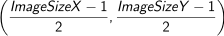
For example, the following image contains 4 pixels. If the formula is applied, the center of the image is found at (1.5, 0.0).
When a function works with subpixel accuracy, you must be especially careful when specifying end points and bounds. For example, to draw a rectangle around the border of an image of width SizeX and height SizeY, using MgraRect(), you must take into account the 0.5 distance from the center of the pixel to its edges. The following images show how a vector based rectangle will be drawn using MgraRect() with and without the correction for subpixel accuracy.

The following code snippet shows the correct positions to specify when drawing a box that completly encloses an image.
/* Specify the size of the buffer. */
MIL_INT SizeX = 5;
MIL_INT SizeY = 4;

MbufAlloc2d(MilSystem, SizeX, SizeY, 8, M_IMAGE + M_DISP +M_PROC, &DstImageBufId);

/* ... */

/* The start positions of the drawn rectangle corrected for subpixel accuracy. */
MIL_DOUBLE XStart = -0.5;
MIL_DOUBLE YStart = -0.5;

/* The end positions of the drawn rectangle corrected for subpixel accuracy. */
MIL_DOUBLE XEnd = SizeX - 0.5;
MIL_DOUBLE YEnd = SizeY - 0.5;

/* Draw a rectangle that encloses the entire buffer. */
MgraRect(ContextGraId, DstImageBufId, XStart, YStart, XEnd, YEnd);
Note that when drawing with MgraRect() directly in an image, the annotations are scaled to the size of a pixel since they are drawn in a rasterized, destructive, way.
Angle convention in MIL
When working in pixel units, you define angles (in degrees) with respect to the pixel coordinate system. In this case, positive angles are always interpreted to be counterclockwise with respect to the positive X-axis.
Therefore, when rotating a point (x, y) around the origin, the 2D rotation matrix that MIL uses is always:
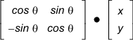
Note that the direction of rotation is inversed from the typical mathematical convention since the Y-axis is oriented downwards. To determine the angle that follows the typical mathematical convention, subtract the angle from 360 (that is, 360 - angle). If you don't convert the angle, the sign of the sine function is inversed from the typical mathematical convention.