MIL Metrology module
- See also

 Availability
 Previous
- Next

Many industries require the ability to measure and validate objects to, for example, assemble multiple parts. Historically, in such industries, manual quality control applications were created to verify the shape, size, and location of objects relative to one another. To accomplish this, a template was used. A template is a physical part, or mold, that typically contains holes and incisions at various positions. If the object being verified physically fit into the template, then that object had passed the quality inspection and could be used in assembly; otherwise, it had failed and would be discarded or reworked. The MIL Metrology module is a powerful set of functions that allows you to design such measurement and validation applications, using a virtual equivalent of a physical template.
The MIL metrology template represents a precisely measured and reusable model from which objects can be verified and measured. To build a metrology template, you must have features (which are like the holes and incisions) and geometric tolerances (which are like the positions that features must have, relative to other features).
You can add either physically measured or constructed features to your metrology template. Physically measured features are geometric primitives (such as a circle) that are physically measured using the edge information (edgels) in the target image. Physically measured features, and the metrology region (ROI) from which their edgels are established in the target image, must be placed at the appropriate location in the template.
Note that Metrology's edgel extraction is based on Edge Finder technology; for more information, see the Extracting the edges section of Chapter 9: Edge Finder.
Constructed features are geometric primitives that do not actually exist in the target image, they are mathematically defined (parametrically constructed features) or geometrically derived from a set of other features (either constructed or physically measured). For example, a constructed point feature can be derived at the center of a physically measured circle.
Features alone do not typically provide enough information to establish the metrology template. For example, if you add two segment features, you might also want to verify their total length, or if they are perpendicular. To do this, you can specify the geometric tolerances that the features of the object in the target image must respect to be considered valid.
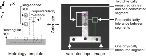
The following example illustrates how you can use features and geometric tolerances in a metrology template to represent an appropriate object in a target image. To depict this object, the template has two ring-shaped metrology regions where two circles are expected to be physically measured, and one rectangular metrology region where one segment is expected to be physically measured. The template also contains the definition of a constructed segment, built from the center points of the two physically measured circles, and a perpendicularity tolerance between this constructed segment and the physically measured segment. The following example also shows the target image, which has been annotated to display the successfully measured features and the validated tolerance.
The MIL Metrology module allows you to specify the coordinates of features and metrology regions relative to a reference frame, which can be set to either the global frame or a local frame.
The global frame is a coordinate system whose origin is at the top-left corner of the metrology template (by default, aligned with the center of the top-left corner pixel of the target image); the global frame is created automatically. A local frame is a coordinate system that can be located anywhere within the metrology template; you can create a local frame at a specified position or based on the positions of other features in the template. During calculation, the reference frame can be repositioned.
The MIL Metrology module provides complete support for camera calibration. If the target image is calibrated, calculations are performed in the calibrated real-world such that, without physically correcting your images, measurements and calculations are made even in the presence of distortion, and results calculated in real-world units.
Note that, when complex distortions exist, some results are meaningless when converted from real-world to pixel units (for example, angle). You should therefore be cautious when using distorted images.
If a camera calibration context has been associated with the target image, you must specify dimensions for features, geometric tolerances, metrology regions, and positions in real-world units.
The MIL Metrology module also allows you to restore a metrology context from a file or memory stream, or save a metrology context to a file or memory stream.