Extracting the edges
- See also

 Availability
 Previous
- Next

-
Consecutive edgels must occupy separate connected pixels.
-
No branches are allowed (they start or end a separate chain).
-
There must not be an edge in the edge map that is more than 1 pixel wide.
Before you write even the simplest application, it is important to have a basic understanding of how Edge Finder extracts edges, and what the differences are between the various types of edges (object contours and line crests). Note that if you are writing slightly more advanced applications, it is also worth having a more in-depth understanding of how edges are calculated.
Basics of edge extraction
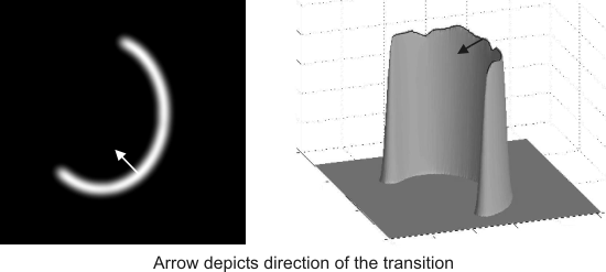
Edge Finder uses operations that are based on differential analysis, where edges (either contours or line crests) are extracted by analyzing intensity transitions in images. Transitions in intensity can come from many physical phenomena, such as shadows and illumination variations. However, strong transitions are typically caused by the presence of an object contour or a line crest in the image, as illustrated below.

Note that the main intensity transition in the image is observed in the perpendicular direction relative to the object border (for an object contour) or line shape (for a line crest).
Edges are extracted in three general steps. First, a filtering process provides an enhanced image of the edges based on the computation of the image's derivatives. Second, detection and thresholding operations determine, from the image enhancement, all pertinent edge elements, or edgels, and accurately calculate their positions. Third, neighboring edgels are connected to build the edge chains (which results in the image's edge map), and features are calculated for each edge. To fit the requirements of your application, Edge Finder allows you to customize each step's corresponding processing controls.
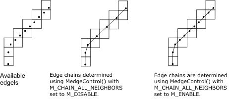
Edgels are connected into edge chains respecting the following constraints, whereby pixels are considered connected based on an 8-connected lattice:
You can control how edgels are connected using MedgeControl() with M_CHAIN_ALL_NEIGHBORS. If the control type is enabled, the chain is created using as much edgel information as possible. If disabled, the chain is created using the least amount of edgel information possible.
Object contours versus line crests
To properly analyze the structures present in an image, it is often useful to consider the image as a topographic surface, where the intensity of each pixel is seen as the elevation value of the surface. By doing so, contours and crests can be more easily understood.
Object contours
An object contour is the inter-pixel boundary that splits into thin layers (delaminates) the separation between the object and the image background, as illustrated below. The edge of the contour is located at the sharpest point within the intensity transition. Moreover, the intensity transition is strongest in the perpendicular direction to the object contour.

Well-defined contours have sharp transitions in value. The smoother the image, the more gradual the change, and the weaker the contour.
To allocate an Edge Finder context for object contours, use MedgeAlloc() with M_CONTOUR.
Line crests
A line crest is the skeleton of a thin curvilinear shape in the image, as illustrated below. The crest is located at the sharpest point of the Gaussian-like profile of the line shape. Moreover, the intensity transition is strongest in the perpendicular direction to the line crest.
Well-defined line crests are thin and have sharp transitions in value. The smoother the image or the larger the lines, the more gradual the change, and the weaker the line crests.
A line crest can either be darker (a valley-like Gaussian profile), lighter (a ridge-like Gaussian profile), or both darker and lighter than the image's background. To specify the color of the line crest to extract, set MedgeControl() with M_FOREGROUND_VALUE to M_FOREGROUND_BLACK, M_FOREGROUND_WHITE, or M_ANY. The default setting is M_FOREGROUND_BLACK.
To allocate an Edge Finder context for line crests, use MedgeAlloc() with M_CREST.
Typically, you should use M_CREST Edge Finder contexts for edges that are established from thin curvilinear shapes; otherwise, you might get unexpected results.
How edges are calculated
For basic applications, you need not know how Edge Finder calculates edges. However, an understanding of this process can help you solve more advanced problems, and adjust some advanced settings.
Object contours
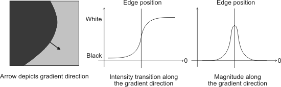
The enhanced image of the object contours is achieved by calculating the gradient magnitude of each pixel in the image. The stronger the intensity transition, the greater the magnitude will be.
The gradient magnitude is calculated at each pixel position from the image's first derivatives. It is defined as:

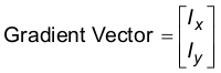
where Ix and Iy are, respectively, the X and Y derivative values. They define the components of the gradient vector as:
An edgel is located at the maximum value of the gradient magnitude over adjacent pixels, in the direction defined by the gradient vector. The gradient direction is the direction of the steepest ascent at an edgel in the image, while the gradient magnitude is the steepness of that ascent. Note that the gradient direction is also the perpendicular direction to the object contour. Well-defined contours are extracted from strong and sharp intensity transitions. Note that a strong contrast between the objects and their background improves the edge detector's robustness and location accuracy.
Note that Edge Finder also supports 3-band images, when extracting object contours. The extraction process is similar to single band images, except the enhanced image of the object contours is achieved by calculating a generalized gradient magnitude of each pixel in the image, for each color band (RGB).
Line crests
The enhanced image of the line crests is achieved by calculating the Hessian magnitude of each pixel in the image. The stronger the crest, the greater the magnitude will be.
The magnitude is defined as the maximum eigenvalue of the Hessian matrix, calculated at each pixel position from the image's second derivatives. The Hessian matrix is defined as:

where Ixx , Iyy and Ixy are, respectively, the X, Y and cross second derivative values of the image.
An edgel is located at the maximum value of the image magnitude over adjacent pixels, in the direction defined by the associated eigenvector. Well-defined line crests are extracted from strong and sharp intensity transitions. Note that a strong contrast between the lines and the image's background improves the edge detector's robustness and the location accuracy.
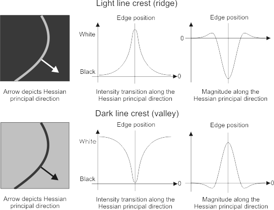
Note that the sign of the magnitude at the crest's edgel locations changes with the color of the line crest. That is, a dark crest has a strong positive magnitude, while a light crest has a strong negative magnitude. The geometric interpretation of the magnitude and its associated orientation is the direction where the crest is the sharpest. Similar to object contours, this direction is also the direction perpendicular to the line crest.