Controlling your lighting device directly or indirectly
You can use the Matrox Iris GT auxiliary signals to control a lighting device that illuminates an object when the camera takes a picture. You can control the lighting device directly using the controlled-current (CCS) output signal (M_AUX_IO9) or indirectly using auxiliary output signal M_AUX_IO4 or M_AUX_IO5 (through a lighting controller that is connected to a lighting device).
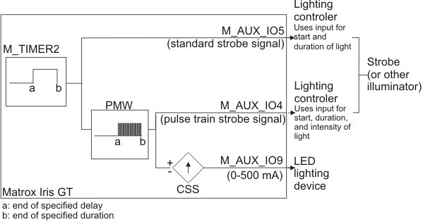
The CCS output signal can supply a varying amount of current, from 0 to 500 mA, for a specified amount of time to a connected LED lighting device; the current supplied controls the intensity of the light emitted by the device. The CCS output signal is controlled by timer 2 (M_TIMER2) and a pulse-width modulator (PWM). The active portion of timer 2's output establishes when and for how long current is supplied. The PWM modulates the active portion so that the resulting pulse train has a duty cycle that is proportional to the specified required intensity of light (using MdigControl() with M_LIGHTING_BRIGHT_FIELD). This resulting signal is then converted into current. Note that the CSS output is automatically output when you enable M_TIMER2; you don't set its source to M_TIMER2 to obtain the output.
Alternatively, you can indirectly control a lighting device (for example, one that requires more than 500 mA), by connecting it to a lighting controller connected to M_AUX_IO4 or M_AUX_IO5. The signal driving the current on the CCS output signal is also routed to M_AUX_IO4 if the source of M_AUX_IO4 is set to M_TIMER2 (referred to as a pulse train strobe signal); while the original timer 2 output is also routed to M_AUX_IO5 if the source of M_AUX_IO5 is set to M_TIMER2 (referred to as a standard strobe signal). Chose M_AUX_IO4 only if your lighting controller can interpret the pulse train arriving during the active portion of the signal and can control the intensity of the connected lighting device accordingly.
For more information about setting up timer 2, refer to the Grabbing with triggers section of Chapter 23: Grabbing with your digitizer. For more information on connecting to the CCS output, M_AUX_IO4, or M_AUX_IO5, refer to the Matrox Iris GT installation and technical reference.
Using either a grab trigger or a continuous grab to start your lighting device
Whenever using a lighting device, it will always start cold (that is, completely discharged) and take a certain amount of time to reach the specified intensity (set using M_LIGHTING_BRIGHT_FIELD). How you account for this cold period when setting up timer 2, depends on how you are grabbing:
-
Continuous (or almost continuous) grabs. If you are grabbing a sequence of images with a negligible amount of delay between one image and the next, you only have to deal with the lighting device being cold at the very beginning of the grab sequence. In this case, you can trigger timer 2 when the camera starts exposing its sensor (using M_TIMER_TRIGGER_SOURCE set to M_EXPOSURE_START).
-
Triggered grabs. If you are grabbing images based on a trigger that might arrive after a non-negligible delay, you will have to account for the lighting device recharging before reaching the specified intensity for each grab. In this case, you should trigger timer 2 upon the grab trigger signal (using M_TIMER_TRIGGER_SOURCE set to M_GRAB_TRIGGER).
Typically, the lighting device should be illuminated for the duration of the camera's exposure time. Unlike with other products, when using the grab trigger signal to trigger timer 2, the specified duration of timer 2's output signal (set using M_TIMER_DURATION + M_TIMER2) specifies how long the timer should remain active during the exposure period (and therefore how long the lighting device should remain active during the exposure period). The active period of timer 2's output will actually start after the specified delay, but the count for how long it should remain active only starts when the camera starts exposing its CCD. Once counting begins, the signal will typically be active for the specified duration. If the duration of timer 2 is greater than the exposure time, timer 2's output signal will end when the exposure time ends (set using M_EXPOSURE_TIME).
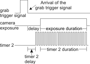
This allows for hardware-specific variances to occur between when the grab trigger signal arrives and when the exposure of the camera's sensor actually starts.
The maximum amount of time it takes for your lighting device to arrive at the required intensity must be probed. This is because the amount of time is hardware-specific, and can vary greatly based on the type of lighting device, the period of the lighting device's reduced activity (caused by significant delays between grab triggers, or long processing delays during MdigProcess()) or inactivity (such as, between individual grabs with MdigGrab()).
When the exposure ends and timer 2 stops outputting an active signal, the lighting device begins to discharge and grow cold. You can reduce the time it takes to bring the lighting device back up to the required intensity by keeping the light at a medium or low intensity (using M_LIGHTING_BRIGHT_FIELD_OFFSET to M_ENABLE).
Controlling your lighting controller and/or the LED lighting device
The following is an example of how to configure a grab using the camera's exposure and timer 2.
MIL_ID MilApplication,  /* Application identifier.  */
       MilSystem,       /* System identifier.       */
       MilDisplay,      /* Display identifier.      */
       MilDigitizer,    /* Digitizer identifier.    */
       MilImage;        /* Image buffer identifier. */

MIL_DOUBLE ExposureTime = 9000 * 1000;
MIL_DOUBLE ExposureTimeDelay = ExposureTime / 3;
MIL_DOUBLE StrobeLength = ExposureTime + ExposureTimeDelay;
MIL_DOUBLE StrobeTimeDelay = 0;
MIL_DOUBLE StrobeLevel = 128;

//Allocate defaults.
MappAllocDefault(M_DEFAULT, &MilApplication, &MilSystem, &MilDisplay,
                 &MilDigitizer, &MilImage);
//Set the grab trigger source to be an external signal.
MdigControl(MilDigitizer, M_GRAB_TRIGGER_SOURCE, M_AUX_IO8);

//Specify to trigger the grab on the falling edge of the grab trigger signal.
//Note that this could be set to the default, which is the same as M_EDGE_RISING.
MdigControl(MilDigitizer, M_GRAB_TRIGGER_ACTIVATION, M_EDGE_FALLING);

//Setup the exposure settings (in nanoseconds)
MdigControl(MilDigitizer, M_EXPOSURE_TIME, ExposureTime);
MdigControl(MilDigitizer, M_EXPOSURE_DELAY, ExposureTimeDelay);

//Invert the timer output.
MdigControl(MilDigitizer, M_TIMER_OUTPUT_INVERTER+M_TIMER2, M_ENABLE);

//Sets the grab trigger source signal as the trigger source.
MdigControl(MilDigitizer, M_TIMER_TRIGGER_SOURCE+M_TIMER2, M_GRAB_TRIGGER);

//Sets a delay before the active portion of the stobe (in nanoseconds).
MdigControl(MilDigitizer, M_TIMER_DELAY+M_TIMER2, StrobeTimeDelay);

//Sets the duration of the active portion of the strobe (in nanoseconds) during the exposure period.
//If set to M_INFINITE, the signal will always be ON.
MdigControl(MilDigitizer, M_TIMER_DURATION+M_TIMER2, StrobeLength);

//Enable timer 2 to output a pulse-train strobe signal and CCS output.
MdigControl(MilDigitizer, M_TIMER_STATE+M_TIMER2, M_ENABLE);

//Sets the intensity level of the strobe (0-255).
MdigControl(MilDigitizer, M_LIGHTING_BRIGHT_FIELD, StrobeLevel);

//Enable the pulse-train strobe signal on M_AUX_IO4.
MsysControl(MilSystem, M_IO_SOURCE + M_AUX_IO4, M_TIMER2);

//Enable the grab trigger.
MdigControl(MilDigitizer, M_GRAB_TRIGGER_STATE, M_ENABLE);

//Grab continuously.
MdigGrabContinuous(MilDigitizer, MilImage);

//Wait.
MosGetch();

//Stop continuous grab.
MdigHalt(MilDigitizer);

//Disable the timer.
MdigControl(MilDigitizer, M_TIMER_STATE+M_TIMER2, M_DISABLE);

//Disable the grab trigger.
MdigControl(MilDigitizer, M_GRAB_TRIGGER_STATE, M_DISABLE);

//Free the defaults.
MappFreeDefault(MilApplication, MilSystem, MilDisplay, MilDigitizer, MilImage);