Polar-to-rectangular and rectangular-to-polar transforms
In a rectangular coordinate system, features or information which are curved can be awkward to read, interpret, or analyze. Transforming such features into a polar coordinate system, where the vertical and horizontal axes represent the radius and the angle respectively, can make it more intuitive or easier to read. With MIL, you can perform rectangular-to-polar or polar-to-rectangular transforms, using the MimPolarTransform() function.
For example, the text on the following image of a disk is easier to read after a rectangular-to-polar transform. The borders of the zone of interest are defined by specifying the center, the start and end radius, and the start and end angle in a source buffer. The function scans the specified zone from the start angle to the end angle. The dotted lines define the borders of the zone of interest:
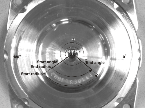
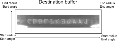
The result will be mapped to the destination buffer as shown below:
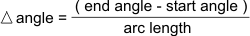
In our example, since the start angle is less than the end angle, the direction of the scan is counter clockwise. The increment in angle is determined by the length, in pixels, of the outside arc, calculated as follows:
The valid range of angles is between -360.0 to 720.0°; there is no maximum span limit. These values are then mapped to a destination buffer.
A polar-to-rectangular transform performs the reverse of the transform described above. It takes a source buffer and maps it to a destination buffer. The center, start angle, end angle, start radius, and end radius parameters are used to specify the position of the contents of the source buffer in the destination buffer.