MimPolarTransform
| MIL_ID SrcImageBufId, | //in |
| MIL_ID DstImageBufId, | //in |
| MIL_DOUBLE CenterPosX, | //in |
| MIL_DOUBLE CenterPosY, | //in |
| MIL_DOUBLE StartRadius, | //in |
| MIL_DOUBLE EndRadius, | //in |
| MIL_DOUBLE StartAngle, | //in |
| MIL_DOUBLE EndAngle, | //in |
| MIL_INT64 OperationMode, | //in |
| MIL_INT64 InterpolationMode, | //in |
| MIL_DOUBLE *DstSizeXPtr, | //out |
| MIL_DOUBLE *DstSizeYPtr | //out |
This function performs a rectangular-to-polar or polar-to-rectangular transformation.
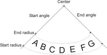
For a rectangular-to-polar transformation set the zone to convert by specifying the center coordinates (CenterPosX and CenterPosY), the start and end radius (StartRadius and EndRadius), and the start and end angle (StartAngle and EndAngle) as follows:

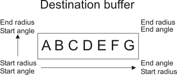
The result will be mapped to the destination buffer as follows:

The increment in angle is determined by the length, in pixels, of the outside arc, calculated as follows:
(endangle - startangle) / arclength.
A polar-to-rectangular transform performs the reverse of the transform described above. It takes a polar buffer and maps it to a rectangular buffer. Use CenterPosX, CenterPosY, StartAngle, EndAngle, StartRadius, EndRadius parameters to specify where in the destination buffer the contents of the polar buffer will be mapped.
Specifies the identifier of the source buffer.
This image buffer must not have a region of interest (ROI) associated with it. Using an image buffer with an ROI will cause an error.
The source image buffer must be unsigned monochrome 8- or 16-bit, M_BGR32 packed, or floating-point.
Specifies the identifier of the destination buffer. To determine the required size of the destination buffer, call the function with DstImageBufId set to M_NULL; in this case, DstSizeXPtr and DstSizeYPtr will return the required X- and Y- size of the buffer, respectively. Note that DstSizeXPtr and DstSizeYPtr will return MIL_DOUBLE values; to allocate an appropriate buffer using these values, you should use a ceiling function, such as ceil(), to obtain the X- and Y- sizes as int values.
This image buffer must not have a region of interest (ROI) associated with it. Using an image buffer with an ROI will cause an error.
Note that after performing the operation, the destination image will not be calibrated, even if the source image was calibrated.
The destination image buffer must be unsigned monochrome 8- or 16-bit, M_BGR32 packed, or floating-point.
Specifies the start of scan in the zone of interest. If the start angle (StartAngle) is less than the end angle (EndAngle), the direction of the scan will be counter clockwise. If the start angle is greater than the end angle, the direction of the scan will be clockwise.
The valid range for StartAngle is between -360.0 to 720.0°. There is no maximum span limit between StartAngle and EndAngle.
Specifies the end of scan in the zone of interest. If the end angle (EndAngle) is greater than the start angle (StartAngle), the direction of the scan will be counter clockwise. If the end angle is less than the start angle, the direction of the scan will be clockwise.
The valid range for EndAngle is between -360.0 to 720.0°. There is no maximum span limit between StartAngle and EndAngle.
Specifies the transform to perform. This parameter must be set to one of the values below.
 For specifying the transform
 |
|||||||||||||||||||||||||||||||||||||||
  Value Value |
Description
|
||||||||||||||||||||||||||||||||||||||
  M_POLAR_TO_RECTANGULAR
 |
Performs polar-to-rectangular transform. |
||||||||||||||||||||||||||||||||||||||
  M_RECTANGULAR_TO_POLAR
 |
Performs rectangular-to-polar transform. (more details...) |
||||||||||||||||||||||||||||||||||||||
Specifies the interpolation used in the conversion.
This parameter must be set to one of the values below.
 For specifying the interpolation used in
the conversion
 |
|||||||||||||||||||||||||||||||||||||||
  Value Value |
Description
|
MIL system-specific tooltip (†) |
 |
 |
 |
 |
 |
 |
 |
 |
 |
 |
 |
 |
 |
 |
 |
 |
 |
 |
 |
||||||||||||||||||
  M_DEFAULT
 |
Default for interpolation mode and type. (more details...) |
† | a | b | c | d | e | f | g | h | i | j | k | l | m | n | o | p | q | r | s | ||||||||||||||||||
  M_BICUBIC
+
 |
Performs bicubic interpolation. (more details...) |
† | a | b | c | e | f | g | h | i | j | k | l | m | n | o | p | q | r | s | |||||||||||||||||||
  M_BILINEAR
+ M_BILINEAR
+ |
Performs bilinear interpolation. (more details...) |
† | a | b | c | d | e | f | g | h | i | j | k | l | m | n | o | p | q | r | s | ||||||||||||||||||
  M_NEAREST_NEIGHBOR
+
 |
Performs nearest neighbor interpolation. (more details...) |
† | a | b | c | d | e | f | g | h | i | j | k | l | m | n | o | p | q | r | s | ||||||||||||||||||
You can add one of the following values to the above-mentioned values to specify how to determine the value of a destination pixel when its associated point falls outside the source buffer.
 For specifying how to determine the value
of a destination pixel when its associated point falls outside the
source buffer
 |
|||||||||||||||||||||||||||||||||||||||
  Combination value Combination value |
Description
|
MIL system-specific tooltip (†) |
 |
 |
 |
 |
 |
 |
 |
 |
 |
 |
 |
 |
 |
 |
 |
 |
 |
 |
 |
||||||||||||||||||
  M_OVERSCAN_CLEAR
 |
Sets the destination pixel to 0. |
† | a | b | c | d | e | f | g | h | i | j | k | l | m | n | o | p | q | r | s | ||||||||||||||||||
  M_OVERSCAN_DISABLE
 |
Leaves the destination pixel as is. |
† | a | b | c | d | e | f | g | h | i | j | k | l | m | n | o | p | q | r | s | ||||||||||||||||||
  M_OVERSCAN_ENABLE M_OVERSCAN_ENABLE |
Uses pixels from the source buffer's ancestor buffer. (more details...) |
† | a | b | c | d | e | f | g | h | i | j | k | l | m | n | o | p | q | r | s | ||||||||||||||||||
| MIL system specific | |||||||||||||||||||||||||||||||||||||||
|
Points falling outside the source image are undefined. |
† | d | j | k | l | m | p | q | r | ||||||||||||||||||||||||||||||
  M_OVERSCAN_FAST
 |
Specifies that MIL will automatically select the overscan that optimizes speed, according to the specified operation and the target system. (more details...) |
† | a | b | c | d | e | f | g | h | i | j | k | l | m | n | o | p | q | r | s | ||||||||||||||||||
| Header | Include mil.h. |
| Library | Use mil.lib; milim.lib. |
| DLL | Requires mil.dll; milim.dll. |