Basic geometric transforms
Image distortions can affect application results. For example, in a medical application that analyzes blood cells, if the camera does not have a one-to-one aspect ratio and no correction is performed, the cells appear distorted and elongated, and incorrect interpretations might result. Rotating such an image causes even more serious object distortion.
To resolve distortion problems, the MIL Image Processing module offers basic, as well as advanced, geometric functions. Since the advanced geometric functions (MimPolarTransform() and MimWarp()) are slower than the basic geometric functions, they should only be used when the required transform cannot be performed using a basic geometric function. For information on the advanced geometric functions, see Chapter 4: Advanced image processing.
Note that MIL-Lite does not support advanced geometric functions, nor does it support rotating, translating, or flipping the image.
In some instances, the orientation of an image can also cause erroneous conclusions. When an object is rotated from its original position, you can realign it in memory by the required angle, using MimRotate(). If the image has prominent edges that identify the right orientation, you can have MIL automatically calculate the required angle of rotation for a proper orientation using MimFindOrientation(). MimFindOrientation() establishes the best orientations based on the edges in your image and calculates the angles at which they occur. You can then call MimRotate() with the angle that was returned with the best score to rotate your image. For more information on finding the dominant orientations of your image, see the Finding dominant image orientations section of Chapter 4: Advanced image processing.
MimTranslate() displaces an image by a specified number of pixels in the x and/or y direction, with subpixel accuracy.
MimFlip() flips an image horizontally (left to right) or vertically (top to bottom). Note that flipping horizontally allows you to get a mirror copy of the original image.
The MimResize() function resizes an image along the horizontal and/or vertical axis. This can help resolve aspect-ratio problems. If both the horizontal and vertical resizing factors are set to the same value, this function can reduce or magnify an image to an appropriate size.
Geometric transformations are performed according to a specified interpolation mode.
The various interpolation modes available in MIL are:
-
A standard nearest neighbor interpolation (M_NEAREST_NEIGHBOR).
-
A standard bilinear interpolation (M_BILINEAR).
-
A standard bicubic interpolation (M_BICUBIC).
-
A weighted average interpolation (M_AVERAGE).
-
An interpolation based on the minimum or maximum pixel value in the specified source image (M_MIN or M_MAX).
When using MimResize() with M_AVERAGE, M_MIN, or M_MAX, the only scaling factors that will work are values of 1 or less.
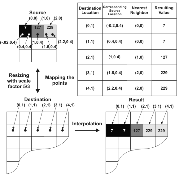
A nearest neighbor interpolation works by first mapping pixel points in the destination image to their corresponding location in the source image. The intensity value of the source pixel closest to the mapped position is then applied to the corresponding destination pixel. No other neighboring values are taken into account (weighted values are not used). In the image below, a source image goes through a resize operation (MimResize()) and then a nearest neighbor interpolation is performed:
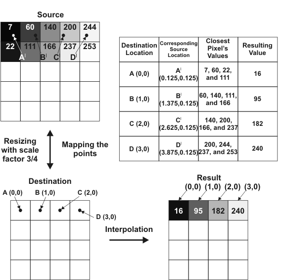
In a bilinear interpolation, the pixel points of the destination image are mapped to their corresponding location in the source image. Then, an intensity value for each point is calculated based on its proximity to source pixels. The calculation performed is a weighted average of the 2 nearest pixels in the X-direction to the target point, and the 2 nearest pixels in the Y direction to the target point. The calculated intensity is then applied to the original destination pixels. Although processing is slightly slower, this results in a smoother and more refined interpolation than when using a nearest neighbor operation. In the example shown below, the source image goes through a resize operation (MimResize()) and then a billinear interpolation is performed:
A bicubic interpolation works in much the same way as a bilinear interpolation. However, the bicubic algorithm is much more complicated and uses a sort of weighted average of the sixteen nearest neighbors to a target destination pixel. This interpolation mode requires a relatively large amount of processing time, but yields the best and most refined results of all the interpolation modes.
If performing a "zoom out" operation (such as a resize operation with a scaling factor less than 1), the M_AVERAGE interpolation mode can typically perform an appropriate interpolation. It takes a weighted average of the source pixel areas that compose the destination pixel. For example, if the source buffer is a 6x6 buffer and you are using a scale factor of 0.66, the destination buffer will be a 4x4 buffer. The area of each destination pixel will correspond to the area of a source pixel as well as the partial area of 3 other source pixels. The weight of each source pixel that contributes to a destination pixel is determined by the area it contributes to the destination pixel. The greater the area that a source pixel contributes to a destination pixel, the larger the weight of the source pixel. In the image below, an image is resized (MimResize()) using an M_AVERAGE interpolation mode):
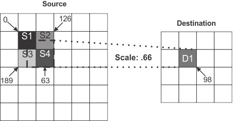
In this case, the destination pixel D1 is composed of the source pixels S1, S2, S3, and S4. The weights of each source pixel depends on their contributing area, and therefore the intensity of D1 will be:
Note that 2.25 is the total area contributed by the source pixels.
In the above example, when solving for the destination pixel's resulting intensity, the following result is obtained:
When using MimResize() with M_INTERPOLATE, a bilinear interpolation is used for "zoom in" resize operations and an averaging interpolation is used for "zoom out" operations. This provides a good quality resulting image and an adequate processing speed.
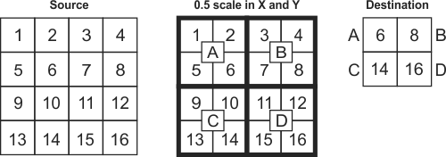
To reduce the size of an image (a "zoom out" procedure), you can also interpolate using the minimum (M_MIN) or maximum (M_MAX) pixel value in the source image area. For example, the following illustration shows a 4x4 source image and its pixel values. A 0.5 scaling factor in X and Y internally divides the image into 4 blocks, each of which has 4 pixels. An M_MAX interpolation uses the highest value of each block to create the 2x2 destination.
If reducing the size of an image with other interpolations (for example, M_AVERAGE) introduces blurriness in certain features you want to preserve, such as text and edges, try using M_MIN or M_MAX. These interpolations are similar to morphological operations. Though they can decrease an object's thickness and amplify noise, they can be effective at maintaining the distinctiveness of certain features.