M3dgraArc
- See also

 Availability
 Function map
- Examples
 M3dgraAlloc
- M3dgraAxis

| MIL_ID List3dgraId, | //in |
| MIL_INT64 ParentLabel, | //in |
| MIL_INT64 CreationMode, | //in |
| MIL_INT64 Symbol, | //in |
| MIL_DOUBLE X1, | //in |
| MIL_DOUBLE Y1, | //in |
| MIL_DOUBLE Z1, | //in |
| MIL_DOUBLE X2, | //in |
| MIL_DOUBLE Y2, | //in |
| MIL_DOUBLE Z2, | //in |
| MIL_DOUBLE X3, | //in |
| MIL_DOUBLE Y3, | //in |
| MIL_DOUBLE Z3, | //in |
| MIL_DOUBLE Angle, | //in |
| MIL_INT64 ControlFlag | //in |
This function adds a circular arc graphic to the specified 3D graphics list, allowing you to, for example, view the circular arc graphic on a 3D display.
You must specify the label of the 3D graphic, in the 3D graphics list, to use as the parent of the arc graphic. When the arc graphic is added to the 3D graphics list's tree structure, it is added as a child under the specified parent. If the 3D graphics list is empty, the arc graphic's parent must be the root node. The coordinates of the arc's vertices are expressed in the coordinate system of the arc graphic's parent.
The arc graphic has its own coordinate system that represents the arc's position and orientation with respect to its parent's coordinate system. The arc's coordinate system's origin is the arc's center, its X-axis is the vector directed from the arc's center to the arc's start point, and its Z-axis is the arc's normal vector. You can inquire the arc's start point and normal vector using M3dgraInquire() with M_START_POINT_... and M_NORMAL..., respectively.
To modify or inquire 3D graphics list settings, use M3dgraControl() or M3dgraInquire(), respectively.
Unlike most other functions that modify a MIL object, you can call this function concurrently from multiple threads on the same MIL 3D graphics list (List3dgraId) without using an M_MUTEX object, as long as all the other parameters of the concurrent calls do not also share data.
Specifies the label of the parent of the arc graphic in the 3D graphics list.
|
For specifying the parent label |
|||||||||||||||||||||||||||||||||||||||
| Description | |||||||||||||||||||||||||||||||||||||||
|
Same as M_ROOT_NODE. |
|||||||||||||||||||||||||||||||||||||||
|
Specifies the top-most node of the 3D graphics list. |
|||||||||||||||||||||||||||||||||||||||
|
Specifies the label of the parent of the arc graphic in the 3D graphics list. Label 0 is the 3D graphics list's root node. (summarize)Specifies the label of the parent of the arc graphic in the 3D graphics list. (more details...) |
|||||||||||||||||||||||||||||||||||||||
Specifies how the arc graphic is defined.
See the Parameter associations section for possible values that can be specified.
Specifies the X-coordinate of the first point used to define the arc.
See the Parameter associations section for possible values that can be specified.
Specifies the Y-coordinate of the first point used to define the arc.
See the Parameter associations section for possible values that can be specified.
Specifies the Z-coordinate of the first point used to define the arc.
See the Parameter associations section for possible values that can be specified.
Specifies the X-coordinate of the second point used to define the arc.
See the Parameter associations section for possible values that can be specified.
Specifies the Y-coordinate of the second point used to define the arc.
See the Parameter associations section for possible values that can be specified.
Specifies the Z-coordinate of the second point used to define the arc.
See the Parameter associations section for possible values that can be specified.
Specifies the X-coordinate of the third point used to define the arc.
See the Parameter associations section for possible values that can be specified.
Specifies the Y-coordinate of the third point used to define the arc.
See the Parameter associations section for possible values that can be specified.
Specifies the Z-coordinate of the third point used to define the arc.
See the Parameter associations section for possible values that can be specified.
Specifies the angle used to define the arc.
Set this parameter to M_DEFAULT if not used.
See the Parameter associations section for possible values that can be specified.
The table below lists possible values for the CreationMode, X1, Y1, Z1, X2, Y2, Z2, X3, Y3, Z3, and Angle parameters.
Set unused parameters to M_DEFAULT.
|
For specifying the arc graphic
|
|||||||||||||||||||||||||||||||||||||||
| Description | |||||||||||||||||||||||||||||||||||||||
| X1 | |||||||||||||||||||||||||||||||||||||||
| Y1 | |||||||||||||||||||||||||||||||||||||||
| Z1 | |||||||||||||||||||||||||||||||||||||||
| X2 | |||||||||||||||||||||||||||||||||||||||
| Y2 | |||||||||||||||||||||||||||||||||||||||
| Z2 | |||||||||||||||||||||||||||||||||||||||
| X3 | |||||||||||||||||||||||||||||||||||||||
| Y3 | |||||||||||||||||||||||||||||||||||||||
| Z3 | |||||||||||||||||||||||||||||||||||||||
| Angle | |||||||||||||||||||||||||||||||||||||||
|
Defines a circular arc graphic using a center and two end points. The result will be a circular arc, with a radius defined by the center and the first end point. The arc extends from the first end point to the point on the line that passes through the center and the second end point. Therefore, the second end point does not have to be a point on the arc. 
Defines a circular arc graphic using a center and two end points. (more details...) |
|||||||||||||||||||||||||||||||||||||||
|
Specifies the X-coordinate of the arc's center. |
|||||||||||||||||||||||||||||||||||||||
|
Specifies the Y-coordinate of the arc's center. |
|||||||||||||||||||||||||||||||||||||||
|
Specifies the Z-coordinate of the arc's center. |
|||||||||||||||||||||||||||||||||||||||
|
Specifies the X-coordinate of the arc's first end point. |
|||||||||||||||||||||||||||||||||||||||
|
Specifies the Y-coordinate of the arc's first end point. |
|||||||||||||||||||||||||||||||||||||||
|
Specifies the Z-coordinate of the arc's first end point. |
|||||||||||||||||||||||||||||||||||||||
|
Specifies the X-coordinate of the arc's second end point. |
|||||||||||||||||||||||||||||||||||||||
|
Specifies the Y-coordinate of the arc's second end point. |
|||||||||||||||||||||||||||||||||||||||
|
Specifies the Z-coordinate of the arc's second end point. |
|||||||||||||||||||||||||||||||||||||||
|
Specifies which angle to use with the specified center and end points. (summarize)Specifies which angle to use with the specified center and end points. (more details...) |
|||||||||||||||||||||||||||||||||||||||
|
Same as M_SMALLEST_ANGLE. |
|||||||||||||||||||||||||||||||||||||||
|
Specifies to use the biggest angle formed by the specified center and end points. |
|||||||||||||||||||||||||||||||||||||||
|
Specifies to use the smallest angle formed by the specified center and end points. |
|||||||||||||||||||||||||||||||||||||||
|
Defines a circular arc graphic using a center and two vectors. The first vector defines the distance between the center and the first end point, and its magnitude determines the arc radius. The second vector defines the distance between the center and the second end point. The result will be a circular arc that extends from the first end point, to the point on the line that passes through the center and the second end point. Therefore, the second end point does not have to be a point on the arc. 
Defines a circular arc graphic using a center and two vectors. (more details...) |
|||||||||||||||||||||||||||||||||||||||
|
Specifies the X-coordinate of the arc's center. |
|||||||||||||||||||||||||||||||||||||||
|
Specifies the Y-coordinate of the arc's center. |
|||||||||||||||||||||||||||||||||||||||
|
Specifies the Z-coordinate of the arc's center. |
|||||||||||||||||||||||||||||||||||||||
|
Specifies the X-component of the first vector. |
|||||||||||||||||||||||||||||||||||||||
|
Specifies the Y-component of the first vector. |
|||||||||||||||||||||||||||||||||||||||
|
Specifies the Z-component of the first vector. |
|||||||||||||||||||||||||||||||||||||||
|
Specifies the X-component of the second vector. |
|||||||||||||||||||||||||||||||||||||||
|
Specifies the Y-component of the second vector. |
|||||||||||||||||||||||||||||||||||||||
|
Specifies the Z-component of the second vector. |
|||||||||||||||||||||||||||||||||||||||
|
Specifies which angle to use with the specified center and end points. (summarize)Specifies which angle to use with the specified center and end points. (more details...) |
|||||||||||||||||||||||||||||||||||||||
|
Same as M_SMALLEST_ANGLE. |
|||||||||||||||||||||||||||||||||||||||
|
Specifies to use the biggest angle formed by the specified center and end points. |
|||||||||||||||||||||||||||||||||||||||
|
Specifies to use the smallest angle formed by the specified center and end points. |
|||||||||||||||||||||||||||||||||||||||
|
Defines a circular arc graphic using a center, a starting vector, a normal vector, and an arc angle. The starting vector defines the direction between the center and the start point, as well as the arc radius. The direction in which the arc extends follows the right-hand rule. If the starting direction vector and the normal vector are not perpendicular, the normal vector is orthogonalized. 
Defines a circular arc graphic using a center, a starting vector, a normal vector, and an arc angle. (more details...) |
|||||||||||||||||||||||||||||||||||||||
|
Specifies the X-coordinate of the arc's center. |
|||||||||||||||||||||||||||||||||||||||
|
Specifies the Y-coordinate of the arc's center. |
|||||||||||||||||||||||||||||||||||||||
|
Specifies the Z-coordinate of the arc's center. |
|||||||||||||||||||||||||||||||||||||||
|
Specifies the X-component of the arc's starting vector. |
|||||||||||||||||||||||||||||||||||||||
|
Specifies the Y-component of the arc's starting vector. |
|||||||||||||||||||||||||||||||||||||||
|
Specifies the Z-component of the arc's starting vector. |
|||||||||||||||||||||||||||||||||||||||
|
Specifies the X-component of the arc's normal vector. |
|||||||||||||||||||||||||||||||||||||||
|
Specifies the Y-component of the arc's normal vector. |
|||||||||||||||||||||||||||||||||||||||
|
Specifies the Z-component of the arc's normal vector. |
|||||||||||||||||||||||||||||||||||||||
|
Specifies the arc angle, in degrees. (summarize)Specifies the arc angle, in degrees. (more details...) |
|||||||||||||||||||||||||||||||||||||||
|
Defines a circular arc graphic using three points on the arc. The arc starts at the first point, passes through the second point, and ends at the third point. 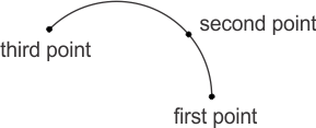
Defines a circular arc graphic using three points on the arc. (more details...) |
|||||||||||||||||||||||||||||||||||||||
|
Specifies the X-coordinate of the first point on the arc. |
|||||||||||||||||||||||||||||||||||||||
|
Specifies the Y-coordinate of the first point on the arc. |
|||||||||||||||||||||||||||||||||||||||
|
Specifies the Z-coordinate of the first point on the arc. |
|||||||||||||||||||||||||||||||||||||||
|
Specifies the X-component of the second point on the arc. |
|||||||||||||||||||||||||||||||||||||||
|
Specifies the Y-component of the second point on the arc. |
|||||||||||||||||||||||||||||||||||||||
|
Specifies the Z-component of the second point on the arc. |
|||||||||||||||||||||||||||||||||||||||
|
Specifies the X-component of the third point on the arc. |
|||||||||||||||||||||||||||||||||||||||
|
Specifies the Y-component of the third point on the arc. |
|||||||||||||||||||||||||||||||||||||||
|
Specifies the Z-component of the third point on the arc. |
|||||||||||||||||||||||||||||||||||||||
| Header | Include mil.h. |
| Library | Use mil.lib; mil3d.lib. |
| DLL | Requires mil.dll; mil3d.dll. |