Filters
Filter values by
Registration object type
  • Registration correlation-stitching context
  • Registration correlation-stitching result buffer
  • Registration photometric stereo context
  • Registration photometric stereo result
  • Registration extended depth of field context
  • Registration depth-from-focus context
  • Registration HDR context
| Customize Help
| Save Settings

MregControl


Function Map
Synopsis
Control a registration context, registration element, or registration result buffer setting.
Syntax
void MregControl(
MIL_ID ContextOrResultId, //in
MIL_INT Index, //in
MIL_INT64 ControlType, //in
MIL_DOUBLE ControlValue //in
)
Description

This function controls the settings of a registration context or a registration result buffer. It also controls the registration elements of a correlation-stitching or photometric stereo registration context. For registration contexts and registration elements, these settings control the execution of MregSetLocation(), MregCalculate(), and/or MregDraw() operations. For correlation-stitching registration result buffers, these settings control the execution of MregDraw() and MregTransformImage() operations.

Use MregInquire() to inquire about control type settings.

Note that when using a C compiler (not a C++ or other compiler) in 64-bit mode, MregControl() internally calls the MIL_DOUBLE version of this function (MregControlDouble()). If you need to pass integer values, call the MIL_INT64 version of this function (MregControlInt64()).
Note that this function reference has not been updated for a MIL system added during a MIL update. Refer to the MIL system's release note to see which MIL system’s documentation you should use in its place and any possible differences.
Parameters
This function is not supported on the selected boards.
This function reference has not been updated for the selected MIL system. To show the content of this page, choose a second MIL system; refer to the MIL system's release note to see which MIL system’s documentation to choose and any possible differences.
Parameters
ContextOrResultId

Specifies the identifier of the registration context or registration result buffer whose settings you can modify; you can only control settings of correlation-stitching or photometric stereo types of registration result buffers. The registration context must have been previously allocated on the system using MregAlloc(). The correlation-stitching or photometric stereo registration result buffer must have been previously allocated on the system using MregAllocResult() with M_STITCHING_RESULT or M_PHOTOMETRIC_STEREO_RESULT.

Index

Specifies that a registration context, an individual registration element (of a correlation-stitching or photometric stereo registration context), or a registration result buffer is controlled. Set this parameter to one of the following values:

function map For the registration context, registration element, or registration result buffer
Click to summarizeValue Description
Click to summarize M_DEFAULT

Specifies the default value.

If an M_STITCHING registration context is specified, same as M_ALL.

If an M_EXTENDED_DEPTH_OF_FIELD, M_DEPTH_FROM_FOCUS, M_HIGH_DYNAMIC_RANGE, or M_PHOTOMETRIC_STEREO registration context is specified, same as M_CONTEXT.

If a registration result buffer is specified, same as M_GENERAL.

(summarize)
Click to summarize M_ALL

Applies the specified control setting to all registration elements, if a correlation-stitching or photometric stereo registration context is specified. Note that this setting is not available for an M_EXTENDED_DEPTH_OF_FIELD, M_DEPTH_FROM_FOCUS, or an M_HIGH_DYNAMIC_RANGE registration context.

(summarize)
Click to summarize M_CONTEXT

Controls a general setting of a registration context, if one is specified.

Click to summarize M_GENERAL

Controls a general setting of a registration result buffer, if one is specified.

Click to summarize 0 < Value < M_NUMBER_OF_REGISTRATION_ELEMENTS

Specifies the index of the individual registration element to control, if a correlation-stitching or a photometric stereo registration context is specified.

Note that this setting is not available for an M_EXTENDED_DEPTH_OF_FIELD or M_DEPTH_FROM_FOCUS registration context.

(summarize)
ControlType

Specifies the setting to change.

See the Parameter associations section for possible values that can be specified.

ControlValue

Specifies the setting's new value.

See the Parameter associations section for possible values that can be specified.

The following ControlType and corresponding ControlValue parameter settings are used to control M_STITCHING or M_PHOTOMETRIC_STEREO registration context settings; in this case, the Index parameter must be set to M_CONTEXT.

function map For operation settings of M_STITCHING or M_PHOTOMETRIC_STEREO registration contexts
Click to summarize
ControlType
Description
ControlValue
Click to summarize M_NUMBER_OF_REGISTRATION_ELEMENTS

Sets the number of registration elements in the registration context. If you reduce the number of registration elements, the settings of the ones that remain are kept unchanged. If you increase the number of registration elements, the new ones are initialized with the default settings.

You should have at least as many registration elements as the number of images that you want to register.

For a photometric stereo registration context, the number of registration elements also corresponds to the maximum number of lights used during the photometric stereo computation. INQ

(summarize)
Click to summarize M_DEFAULT

Specifies the default value. For a correlation-stitching registration context, the default value is 256. For a photometric stereo registration context, the default value is 16.

(summarize)
Click to summarize 2 <= Value < 8192

Specifies the number of registration elements for a correlation-stitching registration context.

Click to summarize Value > 3

Specifies the number of registration elements for a photometric stereo registration context.

The following ControlType and corresponding ControlValue parameter settings are used to control M_STITCHING registration context settings; in this case, the Index parameter must be set to M_CONTEXT.

function map For operation settings of M_STITCHING registration contexts
Click to summarize
ControlType
Description
ControlValue
Click to summarize M_ACCURACY

Sets the accuracy of the registration calculation. Accuracy depends on the image's dynamic range, sharpness, and noise. The best accuracy is achieved for well-contrasted noise-free images. INQ

(summarize)
Click to summarize M_DEFAULT

Same as M_HIGH.

Click to summarize M_HIGH

Specifies high accuracy. Registration will be calculated with subpixel accuracy.

(summarize)
Click to summarize M_LOW

Specifies low accuracy. Registration will be calculated with pixel accuracy.

(summarize)
Click to summarize M_LOCATION_DELTA

Sets the maximum displacement that will be applied to any pixel in the images during registration, relative to its initial location set using MregSetLocation(). With a larger maximum displacement, you can align the images even if the location that was set using MregSetLocation() was not precise. However, this can lead to a longer calculation time.

Note that if you have not set the rough location using MregSetLocation(), set M_LOCATION_DELTA to 100, so that all possible translations are searched. INQ

(summarize)
Click to summarize M_DEFAULT

Specifies the default value; the default value is 5%.

Click to summarize 0.0 < Value <= 100.0

Specifies the maximum displacement as a percentage. The displacement is expressed an a percentage of the biggest dimension of the images to align.

(summarize)
Click to summarize M_MIN_OVERLAP

Sets the minimum overlap that should exist between an image and its reference image so that the registration calculation can optimize the match in their overlapping region. If the minimum overlap is not met, the optimization step will not be performed for this image. Instead, the transformation that was set using MregSetLocation() becomes the optimal transformation.

The image's registration result element will indicate that the registration operation failed for this image. INQ

(summarize)
Click to summarize M_DEFAULT

Specifies the default value; the default value is 20.0%.

Click to summarize 0.0 < Value <= 100.0

Specifies the minimum overlap as a percentage. The overlap is expressed as a percentage of the smallest of the two images.

(summarize)
Click to summarize M_SCORE_TYPE

Sets the type of score calculated during registration. This calculated score can be retrieved after registration using MregGetResult() with M_SCORE. INQ

(summarize)
Click to summarize M_CORRELATION

Specifies to calculate the score based on the normalized grayscale correlation in the overlapped region.

Click to summarize M_NONE

Specifies that no score is calculated; it is set to 100%.

This is the default value.

(summarize)
Click to summarize M_TRANSFORMATION_TYPE

Sets the type of transformation that the registration calculation will use to optimize the match in the images' overlapping regions. INQ

(summarize)
Click to summarize M_DEFAULT

Same as M_TRANSLATION.

Click to summarize M_PERSPECTIVE

Specifies that a perspective warping can be performed to optimize the match in the overlapping regions.

Click to summarize M_TRANSLATION

Specifies that a translation can be performed to optimize the match in the overlapping regions.

Click to summarize M_TRANSLATION_ROTATION

Specifies that a translation and a rotation can be performed to optimize the match in the overlapping regions.

Click to summarize M_TRANSLATION_ROTATION_SCALE

Specifies that a translation, a rotation, and a scale operation can be performed to optimize the match in the overlapping regions.

The following ControlType and corresponding ControlValue parameter settings are used to control settings of registration elements (one or all) of a M_STITCHING registration context.

function map For registration elements (one or all) of an M_STITCHING registration context
Click to summarize
ControlType
Description
ControlValue
Click to summarize M_OPTIMIZE_LOCATION

Sets whether to perform the optimization step of the registration calculation for the registration element's image. If you choose not to perform the optimization calculation, the transformation that you set with MregSetLocation() becomes the optimal transformation for this image. When MregCalculate() is called, the transformation is converted so that it maps the image into the global pixel coordinate system instead of into its reference image's pixel coordinate system. INQ

(summarize)
Click to summarize M_DEFAULT

Same as M_ENABLE.

Click to summarize M_DISABLE

Specifies not to perform the optimization calculation.

Click to summarize M_ENABLE

Specifies to perform the optimization calculation.

Click to summarize M_REFERENCE_X

Sets the X-coordinate of the origin of the image's pixel coordinate system.

This is an advanced control type and changing the origin of an image's pixel coordinate system will affect various aspects of the registration process. This origin is used when specifying the approximate location of the image in its registration element's image (MregSetLocation()); you must specify the location of the origin with respect to the origin of the reference element's image. Similarly, if you use the image to position other images, specify locations relative to this origin. The position of your mosaic in the destination image buffer depends on the mosaic's reference coordinate system (MregControl() with M_MOSAIC_STATIC_INDEX), which can be the coordinate system of a particular image. Finally, you can convert coordinates to and from an image's pixel coordinate system, with MregTransformCoordinate() and MregTransformCoordinateList(). If you modify the origin of an image's pixel coordinate system, you must keep the origin's new location in mind when performing any of these operations. INQ

(summarize)
Click to summarize M_DEFAULT

Specifies that the default X-coordinate of the origin will be used.

The default value is 0.0.

(summarize)
Click to summarize M_CENTER_ELEMENT

Specifies the X-coordinate of the origin to be at the center of the image.

Click to summarize Value

Specifies the X-coordinate of the origin, in pixels. The value can be specified with subpixel accuracy.

(summarize)
Click to summarize M_REFERENCE_Y

Sets the Y-coordinate of the origin of the image's pixel coordinate system.

This is an advanced control type and changing the origin of an image's pixel coordinate system will affect various aspects of the registration process. This origin is used when specifying the approximate location of the image in its registration element's image (MregSetLocation()); you must specify the location of the origin with respect to the origin of the reference element's image. Similarly, if you use this image to position other images, specify locations relative to this origin. The position of your mosaic in the destination image buffer depends on the mosaic's reference coordinate system (MregControl() with M_MOSAIC_STATIC_INDEX), which can be the coordinate system of a particular image. Finally, you can convert coordinates to and from an image's pixel coordinate system, with MregTransformCoordinate() and MregTransformCoordinateList(). If you modify the origin of an image's pixel coordinate system, you must keep the origin's new location in mind when performing any of these operations. INQ

(summarize)
Click to summarize M_DEFAULT

Specifies that the default Y-coordinate of the origin will be used.

The default value is 0.0.

(summarize)
Click to summarize M_CENTER_ELEMENT

Specifies the Y-coordinate of the origin to be at the center of the image.

Click to summarize Value

Specifies the Y-coordinate of the origin, in pixels. The value can be specified with subpixel accuracy.

(summarize)

The following ControlType and corresponding ControlValue parameter settings are used to control the settings of a M_STITCHING_RESULT result buffer; in this case, the Index parameter must be set to M_GENERAL.

function map For M_STITCHING_RESULT result buffers
Click to summarize
ControlType
Description
ControlValue
Click to summarize M_MOSAIC_COMPOSITION

Sets which image's pixel values to use when composing the mosaic and two or more images overlap. INQ

(summarize)
Click to summarize M_DEFAULT

Same as M_LAST_IMAGE.

Click to summarize M_AVERAGE_IMAGE

Specifies to use the average value of the images' pixels in the overlapping region.

Click to summarize M_FIRST_IMAGE

Specifies to use the pixels of the image associated with the registration result element with the lowest index.

Click to summarize M_FUSION_IMAGE

Specifies to fuse the images by progressively blending overlapping pixels. That is, overlapping pixel values are modified (blended) to form a transitional portion. Blending is based on the distance between each pixel and the edges of the images in the mosaic.

(summarize)
Click to summarize M_LAST_IMAGE

Specifies to use the pixels of the image associated with the registration result element with the highest index.

Click to summarize M_SUPER_RESOLUTION

Specifies to use a super-resolution algorithm to create the mosaic.

For best results, the image alignment should be accurate. To perform registration calculations with subpixel accuracy, call MregControl() with M_ACCURACY set to M_HIGH. The source images should be of good quality with clear, distinct features in the overlapping region.

To customize the super-resolution process, set the point-spread function, its radius, and the degree of smoothness to use, with M_SR_PSF_TYPE, M_SR_PSF_RADIUS, and M_SR_SMOOTHNESS respectively.

(summarize)
Click to summarize M_MOSAIC_OFFSET_X

Sets the X-offset between the origin of the coordinate system used to compose the mosaic and the left side of the destination image buffer. The coordinate system used to compose the mosaic is the one specified with M_MOSAIC_STATIC_INDEX. INQ

(summarize)
Click to summarize M_DEFAULT

Same as M_ALIGN_LEFT.

Click to summarize M_ALIGN_LEFT

Specifies that the X-offset (in pixels) will be calculated such that the left-most part of the mosaic will be aligned with the left side of the destination image buffer.

Click to summarize Value

Specifies the X-offset, in pixels.

Click to summarize M_MOSAIC_OFFSET_Y

Sets the Y-offset between the origin of the coordinate system used to compose the mosaic and the top of the destination image buffer. The coordinate system used to compose the mosaic is the one specified with M_MOSAIC_STATIC_INDEX. INQ

(summarize)
Click to summarize M_DEFAULT

Same as M_ALIGN_TOP.

Click to summarize M_ALIGN_TOP

Specifies that the Y-offset (in pixels) will be calculated such that the top-most part of the mosaic will be aligned with the top of the destination image buffer.

Click to summarize Value

Specifies the Y-offset, in pixels.

Click to summarize M_MOSAIC_SCALE

Sets the scale factor to apply to the images before composition of the mosaic. A value greater than 1.0 produces an enlarged mosaic, while a value less than 1.0 produces a reduced one. INQ

(summarize)
Click to summarize 0.0 < Value <= 10.0

Specifies the scale factor.

The default value is 1.0.

(summarize)
Click to summarize M_MOSAIC_STATIC_INDEX

Sets the coordinate system relative to which the mosaic will be composed. This can be a registered image's pixel coordinate system or the global pixel coordinate system. If you select an image's pixel coordinate system, that image will appear upright in the mosaic, and the other images will be oriented relative to it.

By default, the origin of the mosaic will appear at the top-left corner of the destination image buffer. You can adjust the horizontal and vertical offset of the origin using M_MOSAIC_OFFSET_X and M_MOSAIC_OFFSET_Y. INQ

(summarize)
Click to summarize M_DEFAULT

Specifies the default value. By default, the mosaic will be composed with respect to the pixel coordinate system of the image associated with registration result element 0.

(summarize)
Click to summarize M_ALL

Specifies that the coordinate system will be chosen such that the minimum change is done on all images during the mosaic composition. This setting is only available when composing a mosaic with only two images.

(summarize)
Click to summarize M_REGISTRATION_GLOBAL

Specifies that the mosaic will be composed with respect to the global pixel coordinate system.

Click to summarize 0 <= Value < NumberOfElements

Specifies the index of the registration result element whose image's pixel coordinate system will be used as the reference coordinate system.

Click to summarize M_SR_PSF_RADIUS

Sets the radius of the M_CIRCULAR and M_GAUSSIAN point-spread functions (PSF). For M_GAUSSIAN, the radius corresponds to the standard deviation. For M_SQUARE, the radius corresponds to half the size of the square side.

This control type is only taken into account when M_MOSAIC_COMPOSITION is set to M_SUPER_RESOLUTION and M_SR_PSF_TYPE is not set to M_DISABLE. INQ

(summarize)
Click to summarize M_DEFAULT

Specifies the default value; the default value is 0.5 pixels.

Click to summarize Value >= 0.0

Specifies the radius of the PSF, in pixel units at the scale of the source images.

Click to summarize M_SR_PSF_TYPE

Sets the type of point-spread function (PSF) to use during super-resolution calculations to model the blurring in source images.

The point-spread function describes how a small point of light in the world is blurred by the acquisition setup (lens and CCD). Use M_SR_PSF_RADIUS to set the radius of the PSF.

The value of this control type is only taken into account when M_MOSAIC_COMPOSITION is set to M_SUPER_RESOLUTION. INQ

(summarize)
Click to summarize M_DEFAULT

Same as M_GAUSSIAN.

Click to summarize M_CIRCULAR

Specifies to assume a PSF that models blurring of single points of light into uniform circles in the image.

Click to summarize M_DISABLE

Specifies that no PSF should be assumed during super-resolution calculations.

Click to summarize M_GAUSSIAN

Specifies to assume a PSF that models blurring of single points of light into radially symmetric gaussian functions in the image.

Click to summarize M_SQUARE

Specifies to assume a PSF that models blurring of single points of light into symmetric square functions in the image.

Click to summarize M_SR_SMOOTHNESS

Sets the smoothness value to use during super-resolution calculations.

Use a high smoothness value to reduce local variations in the mosaic image. This is useful to prevent artifacts caused by noise in the source images.

Use a low smoothness value when there is little noise in the source image. This is useful to preserve the most detail in your mosaic.

This control type is only taken into account when M_MOSAIC_COMPOSITION is set to M_SUPER_RESOLUTION. INQ

(summarize)
Click to summarize M_DEFAULT

Specifies the default value; the default value is 50.0.

Click to summarize 0.0 <= Value <= 100.0

Specifies the smoothness value.

The following ControlType and corresponding ControlValue parameter settings are used to control M_PHOTOMETRIC_STEREO registration context settings; in this case, the Index parameter must be set to M_CONTEXT.

function map For operation settings of M_PHOTOMETRIC_STEREO registration contexts
Click to summarize
ControlType
Description
ControlValue
Click to summarize M_DRAW_WITH_NO_RESULT

Sets the type of image to draw when using MregCalculate() with RegResultOrImageId set to an image buffer. INQ

(summarize)
Click to summarize M_DEFAULT

Same as M_DRAW_ALBEDO_IMAGE.

Click to summarize M_DRAW_ALBEDO_IMAGE

Specifies to draw the albedo image into the image buffer when using MregCalculate() with RegResultOrImageId set to an image buffer.

The albedo image is a composite image derived from multiple image samples, each with a different lighting perspective. The different lighting perspectives help to show changes in reflectance, especially when a change in material occurs, such as when a scratch reveals an underlying material that differs from the surface material. Small defects become more apparent when reflectance changes are revealed using this technique.

This operation is equivalent to performing MregCalculate() followed by MregDraw() with M_DRAW_ALBEDO_IMAGE, without the need to allocate a result buffer.

(summarize)
Click to summarize M_DRAW_GAUSSIAN_CURVATURE_IMAGE

Specifies to draw the Gaussian curvature image into the image buffer when using MregCalculate() with RegResultOrImageId set to an image buffer.

This operation is equivalent to performing MregCalculate() when M_GAUSSIAN_CURVATURE is set to M_ENABLE followed by MregDraw() with M_DRAW_GAUSSIAN_CURVATURE_IMAGE, without the need to allocate a result buffer.

(summarize)
Click to summarize M_DRAW_LOCAL_CONTRAST_IMAGE

Specifies to draw the local contrast image into the image buffer when using MregCalculate() with RegResultOrImageId set to an image buffer.

This operation is equivalent to performing MregCalculate() when M_LOCAL_CONTRAST is set to M_ENABLE followed by MregDraw() with M_DRAW_LOCAL_CONTRAST_IMAGE, without the need to allocate a result buffer.

(summarize)
Click to summarize M_DRAW_LOCAL_SHAPE_IMAGE

Specifies to draw the local shape image into the image buffer when using MregCalculate() with RegResultOrImageId set to an image buffer.

This operation is equivalent to performing MregCalculate() when M_LOCAL_SHAPE is set to M_ENABLE followed by MregDraw() with M_DRAW_LOCAL_SHAPE_IMAGE, without the need to allocate a result buffer.

(summarize)
Click to summarize M_DRAW_MEAN_CURVATURE_IMAGE

Specifies to draw the mean curvature image into the image buffer when using MregCalculate() with RegResultOrImageId set to an image buffer.

This operation is equivalent to performing MregCalculate() when M_MEAN_CURVATURE is set to M_ENABLE followed by MregDraw() with M_DRAW_MEAN_CURVATURE_IMAGE, without the need to allocate a result buffer.

(summarize)
Click to summarize M_DRAW_TEXTURE_IMAGE

Specifies to draw the texture image into the image buffer when using MregCalculate() with RegResultOrImageId set to an image buffer.

This operation is equivalent to performing MregCalculate() when M_TEXTURE_IMAGE is set to M_ENABLE followed by MregDraw() with M_DRAW_TEXTURE_IMAGE, without the need to allocate a result buffer.

(summarize)
Click to summarize M_GAUSSIAN_CURVATURE

Sets whether to compute the Gaussian curvature image when using MregCalculate() with RegResultOrImageId set to a result buffer.

The Gaussian curvature image reveals defects on smooth surfaces, because surface curvature values change abruptly when a defect occurs on such surfaces. This setting is useful when examining a flat printed surface where the printing can obscure defects. Note that this setting is not suitable for finely textured surfaces. Try M_MEAN_CURVATURE instead. INQ

(summarize)
Click to summarize M_DEFAULT

Same as M_DISABLE.

Click to summarize M_DISABLE

Specifies not to compute the Gaussian curvature image. M_DRAW_GAUSSIAN_CURVATURE_IMAGE becomes unavailable in the draw.

(summarize)
Click to summarize M_ENABLE

Specifies to compute the Gaussian curvature image.

Click to summarize M_LOCAL_CONTRAST

Sets whether to compute the local contrast image when using MregCalculate() with RegResultOrImageId set to a result buffer.

M_LOCAL_CONTRAST reveals surface height variations by increasing the contrast between highlights and shadows. This setting performs morphological operations using M_OBJECT_SIZE to control the number of iterations to perform.

A local contrast operation can remove printed text on flat surface areas in the resulting enhanced image, provided source image illumination is even (equal relative intensities across the light sources). INQ

(summarize)
Click to summarize M_DEFAULT

Same as M_DISABLE.

Click to summarize M_DISABLE

Specifies not to compute the local contrast image. M_DRAW_LOCAL_CONTRAST_IMAGE becomes unavailable in the draw.

(summarize)
Click to summarize M_ENABLE

Specifies to compute the local contrast image.

Click to summarize M_LOCAL_SHAPE

Sets whether to compute the local shape image when using MregCalculate() with RegResultOrImageId set to a result buffer.

A local shape image captures raised and recessed features on a surface that are not apparent with a single image using one light source. Multiple acquisitions using many light sources allow the extraction of structural content not otherwise visible, facilitating further image analysis.

You can control shape smoothness in the resulting image with M_SHAPE_SMOOTHNESS.

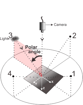
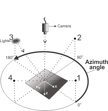
Note that, while each image uses one light source, your lights must be set up in opposite pairs. That is, for each light in the setup, there should be another light positioned 180 degrees opposite. INQ

(summarize)
Click to summarize M_DEFAULT

Same as M_DISABLE.

Click to summarize M_DISABLE

Specifies not to compute the local shape image. M_DRAW_LOCAL_SHAPE_IMAGE becomes unavailable in the draw.

(summarize)
Click to summarize M_ENABLE

Specifies to compute the local shape image.

Click to summarize M_MEAN_CURVATURE

Sets whether to compute the mean curvature image when using MregCalculate() with RegResultOrImageId set to a result buffer.

A mean curvature image can reveal small (local) curvature changes, because the curvature is calculated at every pixel, resulting in more local information. Fine scratches or very small features on a surface are revealed.

Note that the mean curvature operation can substitute for local shape when opposite-paired lighting is not achievable. INQ

(summarize)
Click to summarize M_DEFAULT

Same as M_DISABLE.

Click to summarize M_DISABLE

Specifies not to compute the mean curvature image. M_DRAW_MEAN_CURVATURE_IMAGE becomes unavailable in the draw.

(summarize)
Click to summarize M_ENABLE

Specifies to compute the mean curvature image.

Click to summarize M_NON_UNIFORMITY_CORRECTION

Sets whether to compute a correction for non-uniform illumination on the input image. INQ

(summarize)
Click to summarize M_DEFAULT

Same as M_DISABLE.

Click to summarize M_AUTO

Specifies to compute a correction for non-uniform illumination on the input image. The correction is done without reference images, and uses a pixel neighborhood process. It is recommended to use this setting only when the image illumination is severely non-uniform.

(summarize)
Click to summarize M_DISABLE

Specifies not to compute a correction for non-uniform illumination on the input image.

Click to summarize M_OBJECT_SIZE

Sets the number of iterations to perform when computing a local contrast image (M_LOCAL_CONTRAST or M_DRAW_WITH_NO_RESULT set to M_DRAW_LOCAL_CONTRAST_IMAGE).

For the local contrast operation, M_OBJECT_SIZE controls the number of iterations of a morphological operation. The number of iterations to perform is related to the feature size of the object(s) in the scene. For larger features, more iterations might be needed. The default is 1 iteration, but it is recommended to experiment to find the best setting for your needs. INQ

(summarize)
Click to summarize M_DEFAULT

Specifies the default value; the default value is 1.

Click to summarize Value >= 0

Specifies the number of iterations of morphological operations to perform.

Note that setting a value of zero is permitted. If your scene is mostly flat, try setting M_OBJECT_SIZE to zero. In this case, calculations are performed that do not include morphological operations, resulting in reduced prominence of printed text or imagery on flat surfaces, allowing easier detection of surface defects.

(summarize)
Click to summarize M_SHAPE_NORMALIZATION

Sets whether to perform shape normalization when computing a local shape image (M_LOCAL_SHAPE or M_DRAW_WITH_NO_RESULT set to M_DRAW_LOCAL_SHAPE_IMAGE).

Shape normalization is performed by default. You can choose to disable shape normalization if the region undergoing photometric stereo registration is mostly flat (perpendicular to the camera). Disabling shape normalization can improve results in such instances, because surface normals from flat regions will be ignored. INQ

(summarize)
Click to summarize M_DEFAULT

Same as M_ENABLE.

Click to summarize M_DISABLE

Specifies not to normalize the shape information during local shape computation.

Click to summarize M_ENABLE

Specifies to normalize the shape information during local shape computation.

Click to summarize M_SHAPE_SMOOTHNESS

Sets the shape smoothness value when computing a local shape image (M_LOCAL_SHAPE or M_DRAW_WITH_NO_RESULT set to M_DRAW_LOCAL_SHAPE_IMAGE).

(summarize)
Click to summarize M_DEFAULT

Specifies the default value; the default value is 50.0.

Click to summarize 0.0 <= Value <= 100.0

Specifies the degree of smoothness applied to frontiers between raised and recessed regions. Large values apply more smoothing, and result in suppression of smaller features on an object's surface, making the dominant structure more prominent.

(summarize)
Click to summarize M_TEXTURE_IMAGE

Sets whether to compute the texture image when using MregCalculate() with RegResultOrImageId set to a result buffer.

This operation targets surface luminance and can remove spectral reflections. INQ

(summarize)
Click to summarize M_DEFAULT

Same as M_DISABLE.

Click to summarize M_DISABLE

Specifies not to compute the texture image. M_DRAW_TEXTURE_IMAGE becomes unavailable in the draw.

(summarize)
Click to summarize M_ENABLE

Specifies to compute the texture image.

The following ControlType and corresponding ControlValue parameter settings are used to control M_PHOTOMETRIC_STEREO registration result buffer settings; in this case, the Index parameter must be set to M_GENERAL.

function map For operation settings of M_PHOTOMETRIC_STEREO registration result buffers
Click to summarize
ControlType
Description
ControlValue
Click to summarize M_DRAW_REMAP_FACTOR_MODE

Sets whether to automatically calculate the remap factor, or to use a user-defined value. The remap factor is the factor needed to remap the result of an M_DRAW_GAUSSIAN_CURVATURE_IMAGE, M_DRAW_LOCAL_SHAPE_IMAGE, or M_DRAW_MEAN_CURVATURE_IMAGE operation when the destination is not a 32-bit floating-point image buffer.

This control type is useful when you are performing several of these operations and want to ensure that the same factor is used to remap the results of the operation from 32-bit floating-point data to the data type of the destination buffer (ensuring that the stored results are directly comparable).

If you specify M_USER_DEFINED, and set a remap factor using M_DRAW_REMAP_FACTOR_VALUE, the same remapping will be used to remap the result every time you perform one of the relevant operations. If you specify M_AUTO (or M_DEFAULT), a different remap factor is calculated each time, based on the maximum and minimum values in the result. With M_AUTO, the remap factor is automatically defined so that the entire range of the drawn image is represented.

You can retrieve the automatically defined remap factor value using MregGetResult() with M_RANGE_FACTOR_GAUSSIAN_CURVATURE, M_RANGE_FACTOR_LOCAL_SHAPE, or M_RANGE_FACTOR_MEAN_CURVATURE. INQ

(summarize)
Click to summarize M_DEFAULT

Same as M_AUTO.

Click to summarize M_AUTO

Specifies to automatically calculate the remap factor so that the entire range of the drawn image is represented.

Click to summarize M_USER_DEFINED

Specifies to use the remap factor set with M_DRAW_REMAP_FACTOR_VALUE.

Click to summarize M_DRAW_REMAP_FACTOR_VALUE

Sets the remap factor value when M_DRAW_REMAP_FACTOR_MODE is set to M_USER_DEFINED and the destination is not a 32-bit floating-point image buffer.

Pixel intensities are multiplied by ((2 n - 1)/2) * M_DRAW_REMAP_FACTOR_VALUE , then offset by ((2 n - 1)/2); n is the number of bits per pixel.

When M_DRAW_REMAP_FACTOR_MODE is set to M_AUTO, this value isn't used.

To specify an appropriate remap factor value, it is recommended to obtain the automatically calculated remap factor (using MregGetResult() with M_RANGE_FACTOR_...) for some typical images. If the resulting output is satisfactory, set M_DRAW_REMAP_FACTOR_VALUE to the automatically calculated value. If not, you can try setting the remap factor to a higher value; this increases image contrast and helps to bring out smaller details in the resulting photometric stereo image. INQ

(summarize)
Click to summarize M_DEFAULT

Specifies the default value; the default value is 1.0.

Click to summarize Value > 0.0

Specifies the remap factor.

Click to summarize M_STOP_CALCULATE

Stops the current photometric stereo calculation operation. You must call MregControl() with M_STOP_CALCULATE from another thread of higher priority. Results already available in the result buffer become invalid and will be discarded.

(summarize)
Click to summarize M_DEFAULT

Specifies the default behavior.

The following ControlType and corresponding ControlValue parameter settings are used to control registration elements of a M_PHOTOMETRIC_STEREO registration context; in this case, the Index parameter must be set to M_ALL or a specific value.

Note that you must specify your lights in a counter-clockwise order, starting at the positive X-axis. To illustrate, if you have four lights spaced evenly around a scene, and your first light is placed in line with the X-axis (zero degrees), lights 2, 3, and 4 are placed at 90, 180, and 270 degrees, respectively, and must be specified in the same order.

Note that the origin is located at the center of the plane upon which the object is placed for the photometric stereo registration operation, directly below the camera (assuming the camera is perpendicular to the scene).

function map For registration elements of an M_PHOTOMETRIC_STEREO registration context
Click to summarize
ControlType
Description
ControlValue
Click to summarize M_LIGHT_VECTOR_COMPONENT_1

Sets the first component of the light vector for the specified registration element. When M_LIGHT_VECTOR_TYPE is set to M_SPHERICAL, this component is the polar (zenith) angle. When M_LIGHT_VECTOR_TYPE is set to M_CARTESIAN, this component is the vector's X-coordinate in pixel units. INQ

(summarize)
Click to summarize 0.0 <= Value <= 90.0

Specifies the polar (zenith) angle, in degrees, if the light mode is set to the spherical coordinate system. The polar angle is defined as the angle between the image's normal vector (the primary axis) and the light vector. The polar angle is measured from the vertical; that is, the primary axis is at zero degrees.

The primary axis is the vector that goes from the camera to the image. It is typical for the camera to be perpendicular to the object's surface for this application.

(summarize)
Click to summarize Value

Specifies the X-coordinate of the light vector, if the light mode is set to the Cartesian coordinate system.

Set this value in pixel units, considering the light vector projected onto the XY-plane.

(summarize)
Click to summarize M_LIGHT_VECTOR_COMPONENT_2

Sets the second component of the light vector for the specified registration element. When M_LIGHT_VECTOR_TYPE is set to M_SPHERICAL, this component is the azimuth angle. When M_LIGHT_VECTOR_TYPE is set to M_CARTESIAN, this component is the vector's Y-coordinate in pixel units. INQ

(summarize)
Click to summarize 0.0 <= Value <= 360.0

Specifies the azimuth angle, in degrees, if the light mode is set to the spherical coordinate system. The azimuth angle is the angular distance from the positive X-axis to the light vector when projected on the image's XY-plane; the azimuth angle increases counterclockwise.

(summarize)
Click to summarize Value

Specifies the Y-coordinate of the light vector, if the light mode is set to the Cartesian coordinate system.

Set this value in pixel units, considering the light vector projected onto the XY-plane.

(summarize)
Click to summarize M_LIGHT_VECTOR_COMPONENT_3

Sets the third component of the light vector for the specified registration element.

When M_LIGHT_VECTOR_TYPE is set to M_SPHERICAL, this component is the relative intensity of the light source. If relative light intensity is set to 1.0 for all light sources, each light provides the same intensity to the setup, which is the ideal arrangement. If equal light intensities are not possible, set the strongest light to 1.0 and set the other light intensity values relative to this.

When M_LIGHT_VECTOR_TYPE is set to M_CARTESIAN, this component is the vector's Z-coordinate, specified in a pixel unit equivalent. That is, specify the Z-distance in units equivalent to those used for the X- and Y-coordinates. By default, the Z-axis points downward, so the light source is usually in the negative Z-region of the relative coordinate system. Use an absolute value for this component. INQ

(summarize)
Click to summarize Value >= 0.0

Specifies the value of the third component.

Click to summarize M_LIGHT_VECTOR_TYPE

Sets the coordinate system in which the input light vector is represented. INQ

(summarize)
Click to summarize M_DEFAULT

Same as M_SPHERICAL.

Click to summarize M_CARTESIAN

Specifies that the light vector is defined in the Cartesian coordinate system. Coordinates follow the standard MIL right-hand 3D coordinate system.

The origin is located at the center of the plane upon which the object is placed; that is, directly below the camera. The Z-axis follows the primary axis, along the line from the image's normal vector to the camera.

(summarize)
Click to summarize M_SPHERICAL

Specifies that the light vector is defined in the spherical coordinate system. The components include the polar (zenith) angle, the azimuth angle, and the relative intensity of the light source.

(summarize)

The following ControlType and corresponding ControlValue parameter settings are used to control M_EXTENDED_DEPTH_OF_FIELD registration context settings; in this case, the Index parameter must be set to M_CONTEXT.

function map For operation settings of M_EXTENDED_DEPTH_OF_FIELD registration contexts
Click to summarize
ControlType
Description
ControlValue
Click to summarize M_CIRCLE_OF_CONFUSION_RADIUS_MAX

Sets the maximum radius of the circle of confusion (blurring circle), among the input images. If this control type is set incorrectly, the EDoF image might not be completely in focus, even if it should be possible given the input images. INQ

(summarize)
Click to summarize M_DEFAULT

Specifies the default value; the default value is 8 pixels.

Click to summarize 1 <= Value <= 256

Specifies the maximum radius of the circle of confusion (blurring circle) in pixels.

Click to summarize M_MODE

Sets the computation mode of the extended depth of field operation. INQ

(summarize)
Click to summarize M_DEFAULT

Same as M_RECONSTRUCTION.

Click to summarize M_FAST

Specifies a faster computation mode. Note that using a faster computation mode can decrease robustness of the registration operation.

(summarize)
Click to summarize M_RECONSTRUCTION

Specifies a computation mode that favors the quality of the extended depth of field (EDoF) image. This setting can lead to longer computation times.

(summarize)
Click to summarize M_TRANSLATION_TOLERANCE

Sets the maximum distance between a point of an object that is in focus in one image, and the same point in an image in which the object is out of focus, in pixels. If this control type is set incorrectly, the EDoF image might not be completely in focus, even if it should be possible given the input images. INQ

(summarize)
Click to summarize M_DEFAULT

Specifies the default value; the default value is 1 pixel.

Click to summarize 1 <= Value <= 4

Specifies the maximum translation distance of a point between two images, in pixels.

The following ControlType and corresponding ControlValue parameter settings are used to control M_DEPTH_FROM_FOCUS registration context settings; in this case, the Index parameter must be set to M_CONTEXT.

function map For operation settings of M_DEPTH_FROM_FOCUS registration contexts
Click to summarize
ControlType
Description
ControlValue
Click to summarize M_ADAPTIVE_INTENSITY_DELTA

Sets the maximum difference between the intensity values for an object in an image. This value is used when performing the intensity component of an M_ADAPTIVE regularization. This determines whether neighboring pixels are considered part of the same object when using M_ADAPTIVE regularization mode. INQ

(summarize)
Click to summarize M_DEFAULT

Specifies the default value; the default value is 50.0.

Click to summarize Value > 0.0

Specifies the maximum difference of intensities.

Click to summarize M_ADAPTIVE_SMOOTHING

Sets which neighborhood pixels are given more weight when performing the smoothing component of the adaptive regularization. This determines how neighborhood pixels are weighted when using an M_ADAPTIVE regularization mode. INQ

(summarize)
Click to summarize M_DEFAULT

Specifies the default value; the default value is 3.0 pixels.

Click to summarize Value > 0.0

Specifies a distance, in pixels, from the pixel being evaluated. Neighborhood pixels that are within this distance from the pixel being evaluated are given more weight. A lower adaptive smoothing value gives more weight to pixels closer to the pixel being evaluated; while a higher adaptive smoothing value equalizes the weight given to pixels in the neighborhood. If the distance is larger than the regularization neighborhood (M_REGULARIZATION_SIZE), any pixels outside of the regularization neighborhood will have a weight of 0.

(summarize)
Click to summarize M_CONFIDENCE_MAP

Sets whether the confidence map is computed. INQ

(summarize)
Click to summarize M_DEFAULT

Same as M_DISABLE.

Click to summarize M_DISABLE

Specifies that the confidence map is not computed.

Click to summarize M_ENABLE

Specifies that the confidence map is computed.

Click to summarize M_FOCUS_DEPTH_SIZE

Sets the number of images for a portion of the image to go from out of focus to in focus, to out of focus again. A larger number of images indicates a more precise operation, and a longer processing time. INQ

(summarize)
Click to summarize M_DEFAULT

Specifies the default value; the default value is 3 images.

Click to summarize Value > 1

Specifies the number of images.

Click to summarize M_INTENSITY_MAP

Sets whether the intensity map is computed. INQ

(summarize)
Click to summarize M_DEFAULT

Same as M_DISABLE.

Click to summarize M_DISABLE

Specifies that the intensity map is not computed.

Click to summarize M_ENABLE

Specifies that the intensity map is computed.

Click to summarize M_REGULARIZATION_MODE

Sets the mode of regularization. The mode establishes how to adjust the coherency of neighboring pixels in the index map. INQ

(summarize)
Click to summarize M_DEFAULT

Same as M_AVERAGE.

Click to summarize M_ADAPTIVE

Specifies that the regularization takes into account the local geometry and the change in intensity of the content in the source image. This regularization mode is made up of two components: the smoothing (M_ADAPTIVE_SMOOTHING) and the intensity (M_ADAPTIVE_INTENSITY_DELTA) components.

(summarize)
Click to summarize M_AVERAGE

Specifies that the regularization takes into account the average dominance of neighboring pixels.

Click to summarize M_DISABLE

Specifies that the regularization is based on the raw pixel values and that no post-processing is done to ensure the coherency of neighboring pixels.

Click to summarize M_REGULARIZATION_SIZE

Sets the neighborhood size when regularization is used. The neighborhood should be the size of the minimum texture pattern in an object in the image, but no larger than the smallest object dimension in the image. INQ

(summarize)
Click to summarize M_DEFAULT

Specifies the default value; the default value is 5 pixels.

Click to summarize Value >= 3

Specifies the size of the neighborhood, in pixels. The size of the neighborhood used is always an odd number. If you specify an even number, the next largest odd number is applied.

(summarize)

The following ControlType and corresponding ControlValue parameter settings are used to control M_HIGH_DYNAMIC_RANGE registration context settings; in this case, the Index parameter must be set to M_CONTEXT.

function map For operation settings of M_HIGH_DYNAMIC_RANGE registration contexts
Click to summarize
ControlType
Description
ControlValue
Click to summarize M_FUSION_COVERAGE

Sets the required coverage ratio for a successful merge of each source image into the intermediate, working HDR image. The specified value is the ratio between the number of selected pixels and the total number of usable pixels, from 0.0-1.0. The number of selected pixels is the calculated merge area where pixel values are non-saturated in the current source image and still being modified in the working HDR image; these areas are established with the limits set with M_FUSION_LOW_THRESHOLD and M_FUSION_HIGH_THRESHOLD. The total number of usable pixels equals the source image area (M_SIZE_X x M_SIZE_Y). The operation affects only those pixels that are within range.

The M_FUSION_COVERAGE ratio determines the number of pixels used to calculate the gain applied to the source image to successfully merge it with the intermediate, working HDR image. If the source image gives a calculated ratio that is below the specified ratio, the addition of this image to the final HDR image fails. INQ

(summarize)
Click to summarize M_DEFAULT

Specifies the default value; the default value is 0.05.

Click to summarize 0.0 <= Value <= 1.0

Specifies the fusion coverage ratio.

Click to summarize M_FUSION_HIGH_THRESHOLD

Sets the threshold to filter out the saturated pixels (that is, the near maximum values) of the current source image. Specify the threshold as a percentage of the current working range of pixel values, which widens with each source image that is merged into the intermediate, working HDR image. This threshold is also used to establish which pixels are still being modified in the intermediate, working HDR image.

Note that, as the operation proceeds, the last images processed are those taken using the shortest exposures. These are the images with more detail evident in brighter areas, in which fewer saturated (overexposed) pixels fall above the high threshold for exclusion. The final HDR image can include pixels with a maximum intensity value. INQ

(summarize)
Click to summarize M_DEFAULT

Specifies the default value; the default value is 95.0%.

Click to summarize 0.0 <= Value <= 100.0

Specifies the fusion high threshold, as a percentage.

Click to summarize M_FUSION_LOW_THRESHOLD

Sets the threshold to filter out the underexposed pixels (that is, the near 0 values) of the current source image. Specify the threshold as a percentage of the current working range of pixel values, which widens with each source image that is merged into the intermediate, working HDR image. This threshold is also used to establish which pixels are still being modified in the intermediate, working HDR image.

The first source image becomes the working HDR image; no thresholds are applied to this first image. Subsequent source images are evaluated using the limits set with M_FUSION_LOW_THRESHOLD and M_FUSION_HIGH_THRESHOLD.

Also note that the first images to which the operation applies are those taken with the longest exposures, where dark area details are visible, and bright area details are missing due to overexposure. For these images, the operation keeps non-saturated pixels in the darker areas. As the operation continues with subsequent images taken with shorter exposures, more darker pixels will fall below the low threshold and be excluded from the final HDR image. INQ

(summarize)
Click to summarize M_DEFAULT

Specifies the default value; the default value is 5.0%.

Click to summarize 0.0 <= Value <= 100.0

Specifies the fusion low threshold, as a percentage.

Click to summarize M_FUSION_MODE

Sets the criteria by which source image pixels are selected for contribution to the HDR image calculation. Saturated and underexposed pixels are excluded, and the remaining pixels are then used to calculate the gain to apply to the source image to successfully merge it with the intermediate, working HDR image. INQ

(summarize)
Click to summarize M_DEFAULT

Specifies the default value; the default value is M_PERCENTILE_VALUE + M_IN_RANGE.

Click to summarize M_PERCENTILE_VALUE +

Specifies to eliminate from the calculation those pixels whose values exceed or fall short of the limits set with M_FUSION_HIGH_THRESHOLD and M_FUSION_LOW_THRESHOLD, respectively.


You must specify a combination value from the following table:
(summarize)
Click to summarize M_TONE_MAPPING_COEFFICIENT

Sets the tone mapping coefficient when calculating the tone-mapped HDR image.

The specified M_TONE_MAPPING_COEFFICIENT affects the pixel intensity distribution during the tone mapping between the HDR image and the end image. A higher value (closer to 1.0) gives a broader intensity range to bright areas, improving bright area detail and lowering the overall brightness of the final image. Conversely, a lower value (closer to 0.0), gives a broader intensity range to dark areas, improving dark area detail and increasing the overall brightness of the final image. INQ

(summarize)
Click to summarize M_DEFAULT

Specifies the default value; the default value is 0.5.

Click to summarize 0.0 <= Value <= 1.0

Specifies the tone mapping coefficient.

Click to summarize M_TONE_MAPPING_HIGH_THRESHOLD

Sets the tone mapping high threshold to use when calculating the tone-mapped HDR image. Specify the threshold as a percentage of the source image's pixel intensity levels. This removes unnecessary pixel intensity levels at the saturated end, and allows more intensity distribution elsewhere in the image.

For example, if you set the tone mapping high threshold to 90%, pixels in the raw HDR image with intensities in the brightest 10% are excluded. INQ

(summarize)
Click to summarize M_DEFAULT

Specifies the default value; the default value is 99.0.

Click to summarize 0.0 <= Value <= 100.0

Specifies the tone mapping high threshold, as a percentage.

Click to summarize M_TONE_MAPPING_LOW_THRESHOLD

Sets the tone mapping low threshold to use when calculating the tone-mapped HDR image. Specify the threshold as a percentage of the source image's pixel intensity levels. This removes unnecessary pixel intensity levels at the near-zero end, and allows more intensity distribution elsewhere in the image.

For example, if you set the tone mapping low threshold to 10%, pixels in the raw HDR image with intensities in the darkest 10% are excluded. INQ

(summarize)
Click to summarize M_DEFAULT

Specifies the default value; the default value is 1.0.

Click to summarize 0.0 <= Value <= 100.0

Specifies the tone mapping low threshold, as a percentage.

Click to summarize M_TONE_MAPPING_MODE

Sets the tone mapping mode to use when calculating the tone-mapped HDR image. Tone mapping distributes pixel intensity values within the specified range. You can also specify to disable tone mapping (M_DISABLE), in which case the raw HDR image is drawn into the destination buffer.

Note that, when writing results to a result buffer (using MregCalculate()), the raw HDR image is always available to draw (using MregDraw() with M_DRAW_HDR_FULL_IMAGE), whether or not tone mapping was applied. Use MregDraw() with M_DRAW_HDR_IMAGE to draw the tone-mapped HDR image.

When enabled, the tone mapping result is written to the result buffer or the image buffer passed to MregCalculate() or MregDraw(). INQ

(summarize)
Click to summarize M_DEFAULT

Specifies the default value; the default value is M_PERCENTILE_VALUE + M_IN_RANGE.

Click to summarize M_DISABLE

Specifies not to use a tone mapping mode.

Click to summarize M_PERCENTILE_VALUE +

Specifies to apply tone mapping to source image pixels whose intensity levels fall within the limits set with M_TONE_MAPPING_HIGH_THRESHOLD and M_TONE_MAPPING_LOW_THRESHOLD, respectively.

Tone mapping uses specified percentages to calculate upper and lower limits for the operation. To specify explicit values instead of percent thresholds, use MgenLutFunction() with M_TONE_MAPPING to generate the mapping, and then use, for example, MimLutMap() to map the raw HDR image. Note that M_TONE_MAPPING_LOW_THRESHOLD corresponds to a, M_TONE_MAPPING_HIGH_THRESHOLD corresponds to b, and M_TONE_MAPPING_COEFFICIENT corresponds to c.


You must specify a combination value from the following table:
(summarize)
Combination value for M_PERCENTILE_VALUE (when ControlType=M_FUSION_MODE and ControlValue=M_PERCENTILE_VALUE); M_PERCENTILE_VALUE (when ControlType=M_TONE_MAPPING_MODE and ControlValue=M_PERCENTILE_VALUE).

You must add the following value to the above-mentioned values to specify a threshold condition.

function map For specifying a threshold condition
Click to summarizeCombination value Description
Click to summarize M_IN_RANGE

Specifies to apply the fusion or tone mapping to pixels within a specified range. Set the bounds of the range with M_FUSION_LOW_THRESHOLD and M_FUSION_HIGH_THRESHOLD, or with M_TONE_MAPPING_LOW_THRESHOLD and M_TONE_MAPPING_HIGH_THRESHOLD.

(summarize)

The following ControlType and corresponding ControlValue parameter settings are used to control the timeout value for any registration context setting (M_DEPTH_FROM_FOCUS, M_EXTENDED_DEPTH_OF_FIELD, M_HIGH_DYNAMIC_RANGE, M_PHOTOMETRIC_STEREO, or M_STITCHING registration context); in this case, the Index parameter must be set to M_CONTEXT.

function map For operation timeout settings of any registration context
Click to summarize
ControlType
Description
ControlValue
Click to summarize M_TIMEOUT

Sets the timeout value for MregCalculate().

(summarize)
Click to summarize M_DEFAULT

Specifies the default value; the default value is 2000.0 msec.

Click to summarize M_DISABLE

Specifies that there is no timeout value.

Click to summarize Value

Specifies the timeout value, in msec.

Type-specific versions of the function when using a C compiler under 64-bit
void MregControlInt64 (MIL_ID ContextOrResultId, MIL_INT Index, MIL_INT64 ControlType, MIL_INT64 ControlValue)
Parameters

ContextOrResultId

See ContextOrResultId of the main function for a description.

Index

See Index of the main function for a description.

ControlType

See ControlType of the main function for a description.

ControlValue

See ControlValue of the main function for a description.

void MregControlDouble (MIL_ID ContextOrResultId, MIL_INT Index, MIL_INT64 ControlType, MIL_DOUBLE ControlValue)
Parameters

ContextOrResultId

See ContextOrResultId of the main function for a description.

Index

See Index of the main function for a description.

ControlType

See ControlType of the main function for a description.

ControlValue

See ControlValue of the main function for a description.

Compilation information
Header Include mil.h.
Library Use mil.lib; milreg.lib.
DLL Requires mil.dll; milreg.dll.
DEFAULT ALL CONTEXT GENERAL NUMBER OF REGISTRATION ELEMENTS NUMBER OF REGISTRATION ELEMENTS DEFAULT ACCURACY DEFAULT HIGH LOW LOCATION DELTA DEFAULT MIN OVERLAP DEFAULT SCORE TYPE CORRELATION NONE TRANSFORMATION TYPE DEFAULT PERSPECTIVE TRANSLATION TRANSLATION ROTATION TRANSLATION ROTATION SCALE OPTIMIZE LOCATION DEFAULT DISABLE ENABLE REFERENCE X DEFAULT CENTER ELEMENT REFERENCE Y DEFAULT CENTER ELEMENT MOSAIC COMPOSITION DEFAULT AVERAGE IMAGE FIRST IMAGE FUSION IMAGE LAST IMAGE SUPER RESOLUTION MOSAIC OFFSET X DEFAULT ALIGN LEFT MOSAIC OFFSET Y DEFAULT ALIGN TOP MOSAIC SCALE MOSAIC STATIC INDEX DEFAULT ALL REGISTRATION GLOBAL SR PSF RADIUS DEFAULT SR PSF TYPE DEFAULT CIRCULAR DISABLE GAUSSIAN SQUARE SR SMOOTHNESS DEFAULT DRAW WITH NO RESULT DEFAULT DRAW ALBEDO IMAGE DRAW GAUSSIAN CURVATURE IMAGE DRAW LOCAL CONTRAST IMAGE DRAW LOCAL SHAPE IMAGE DRAW MEAN CURVATURE IMAGE DRAW TEXTURE IMAGE GAUSSIAN CURVATURE DEFAULT DISABLE ENABLE LOCAL CONTRAST DEFAULT DISABLE ENABLE LOCAL SHAPE DEFAULT DISABLE ENABLE MEAN CURVATURE DEFAULT DISABLE ENABLE NON UNIFORMITY CORRECTION DEFAULT AUTO DISABLE OBJECT SIZE DEFAULT SHAPE NORMALIZATION DEFAULT DISABLE ENABLE SHAPE SMOOTHNESS DEFAULT TEXTURE IMAGE DEFAULT DISABLE ENABLE DRAW REMAP FACTOR MODE DEFAULT AUTO USER DEFINED DRAW REMAP FACTOR VALUE DEFAULT STOP CALCULATE DEFAULT LIGHT VECTOR COMPONENT 1 LIGHT VECTOR COMPONENT 2 LIGHT VECTOR COMPONENT 3 LIGHT VECTOR TYPE DEFAULT CARTESIAN SPHERICAL CIRCLE OF CONFUSION RADIUS MAX DEFAULT MODE DEFAULT FAST RECONSTRUCTION TRANSLATION TOLERANCE DEFAULT ADAPTIVE INTENSITY DELTA DEFAULT ADAPTIVE SMOOTHING DEFAULT CONFIDENCE MAP DEFAULT DISABLE ENABLE FOCUS DEPTH SIZE DEFAULT INTENSITY MAP DEFAULT DISABLE ENABLE REGULARIZATION MODE DEFAULT ADAPTIVE AVERAGE DISABLE REGULARIZATION SIZE DEFAULT FUSION COVERAGE DEFAULT FUSION HIGH THRESHOLD DEFAULT FUSION LOW THRESHOLD DEFAULT FUSION MODE DEFAULT PERCENTILE VALUE TONE MAPPING COEFFICIENT DEFAULT TONE MAPPING HIGH THRESHOLD DEFAULT TONE MAPPING LOW THRESHOLD DEFAULT TONE MAPPING MODE DEFAULT DISABLE PERCENTILE VALUE IN RANGE TIMEOUT DEFAULT DISABLE CONTEXT GENERAL DEFAULT GENERAL CONTEXT GENERAL CONTEXT DEFAULT