Surface feature enhancement and defect detection using photometric stereo registration
- See also

 Availability
 Previous
- Next

-
Allocate a photometric stereo registration context, using MregAlloc() with M_PHOTOMETRIC_STEREO.
-
Optionally, allocate a photometric stereo registration result buffer to hold the results of the registration operation, using MregAllocResult() with M_PHOTOMETRIC_STEREO_RESULT. If you are only interested in one of the resulting photometric stereo images, you don't need a result buffer.
-
If necessary, allocate an image buffer to hold the resulting image (alternatively, the image can be stored in the result buffer). The image buffer should be of the same size, type, and number of bands as the input images.
-
Set the type of photometric stereo image(s) to calculate, using MregControl(), depending on whether a result buffer or image buffer will hold the resulting photometric stereo image(s):
-
For a result buffer, you can enable one or more types of photometric stereo images for calculation using their dedicated control types. For example, enable a local shape operation using MregControl() with M_LOCAL_SHAPE and M_ENABLE.
-
For an image buffer, specify the photometric stereo image(s) to calculate, using MregControl() with M_DRAW_WITH_NO_RESULT and the appropriate control value (for example, M_DRAW_LOCAL_SHAPE_IMAGE for a local shape image).
-
-
Specify the position of the light used for each input image using MregControl() with M_LIGHT_VECTOR_COMPONENT_1, M_LIGHT_VECTOR_COMPONENT_2, and M_LIGHT_VECTOR_COMPONENT_3.
You must specify your lights in a counter-clockwise order, starting at the positive X-axis. To illustrate, if you have four lights spaced evenly around a scene, and your first light is placed in line with the X-axis (zero degrees), lights 2, 3, and 4 are placed at 90, 180, and 270 degrees, respectively, and must be specified in the same order.
-
Specify any additional control settings (for example, M_SHAPE_SMOOTHNESS for a local shape image) using MregControl().
-
If necessary, specify remap factor settings. The remap factor applies when writing results to a result buffer for a local shape, Gaussian curvature, or mean curvature operation.
-
Set up an array with the identifiers of image buffers that hold the input images. All the images should be of the same scene, taken with all the same camera settings except lighting, and in buffers of the same size, type, and number of bands.
-
Perform the photometric stereo operation, using MregCalculate() with M_COMPUTE, the input image array, and either a destination image or a result buffer.
-
If necessary, retrieve the required results from the result buffer using MregGetResult().
-
If you passed a result buffer to MregCalculate(), you can draw the photometric stereo image(s) from the result buffer into an image buffer using MregDraw(). To draw any resulting image, you must have previously enabled the calculation of that image using MregControl() as discussed above. Note that you do not have to enable an albedo image; it is always available to draw from the result buffer after MregCalculate() is called. Drawable images include but are not limited to a local shape image (M_DRAW_LOCAL_SHAPE_IMAGE) and a Gaussian curvature image (M_DRAW_GAUSSIAN_CURVATURE_IMAGE). Use MregGetResult() to establish the size and type of the image buffer required to draw each of the resulting images.
-
If necessary, save your registration context, using MregSave() or MregStream().
-
Free your allocated registration objects, using MregFree().
-
A local shape image operation (M_LOCAL_SHAPE) captures raised and recessed features on a surface. The operation is fast with minimal noise in the resulting image. Embossed text often shows up well, which can facilitate MIL SureDotOCR and String Reader operations. Use M_SHAPE_SMOOTHNESS to control shape smoothness in the photometric stereo result.
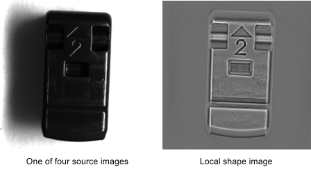
Note how the raised and recessed surfaces on the object are revealed with the local shape operation.
If opposite-paired lighting is not available for a local shape operation, a mean curvature operation can give similar, and sometimes better, results.
-
An albedo image operation (M_DRAW_ALBEDO_IMAGE) highlights changes in surface reflectance, and is useful for finding a defect that reveals an underlying material that reflects differently than the surface material. Any change in surface reflectance, such as from shiny to dull, should be apparent in an albedo image result.
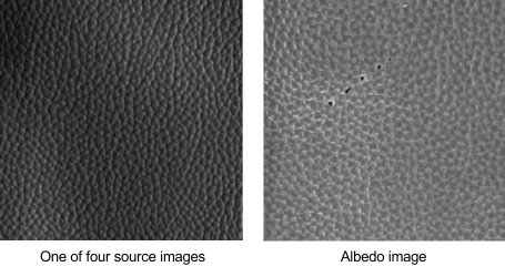
Note the scratch revealed by the albedo image operation.
-
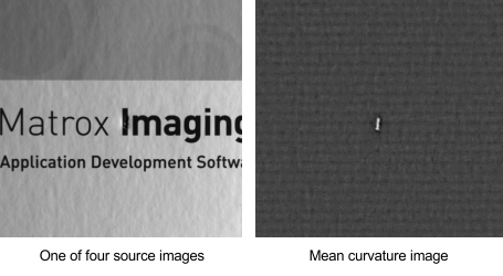
A Gaussian curvature image operation (M_GAUSSIAN_CURVATURE) reveals sharp curvature changes, such as the corner of an object or a puncture in an otherwise flat surface. This operation will not pick up fine curvature detail. Also, if a surface contains flat printed areas, such as text or a logo, M_GAUSSIAN_CURVATURE ignores those differences, since a change in curvature is what matters.

Note how the printed text no longer obscures the defect, which is a large change in the surface curvature. A Gaussian curvature operation will not detect subtle surface curvature differences, such as the paper texture in the source image.
-
The mean curvature image operation (M_MEAN_CURVATURE) can reveal small (local) curvature changes, because the curvature is calculated at every pixel, resulting in more local information. Fine scratches or very small features on a surface are revealed.
The operation reveals the defect while also showing finer surface features (the paper texture above). As with the Gaussian curvature operation, a mean curvature result is not sensitive to printed text.
Note that the above result image was obtained using opposite-paired lighting, which is not required for the mean curvature operation, but is required for local shape results. Therefore, the mean curvature can substitute for local shape when opposite-paired lighting is not achievable.
-
The local contrast image operation (M_LOCAL_CONTRAST) reveals surface height variations by increasing the contrast between highlights and shadows. A local contrast operation can remove printed text on flat surface areas in the resulting enhanced image, provided source image illumination is even (equal relative intensities across the light sources). This operation performs morphological operations using M_OBJECT_SIZE to control the number of iterations to perform. The number of iterations to perform is related to the feature size of the object(s) in the scene. For larger features, more iterations might be needed. The default is 1 iteration, but it is recommended to experiment to find the best setting for your needs.
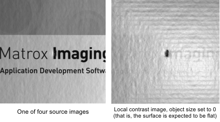
Using the same source images as the Gaussian curvature operation, a local contrast operation reveals the defect and removes or reduces the printed text, while still showing surface texture.
-
A texture image operation (M_TEXTURE_IMAGE) will show printing on a surface, since surface luminance is targeted. This operation can remove spectral reflections, such as those from plastic wrapping. For example, the printed address on a magazine wrapped in plastic becomes readable because the spectral reflections, which otherwise obscure the printing, are removed.

The texture image operation has removed spectral reflections, rendering the printed text and bar code readable in the photometric stereo result.
-
Use the Pattern Matching or Model Finder module to define a model from the start image.
-
Find the model in the end image.
-
Using the model's location in the start and end images, calculate the model's displacement per photometric stereo image. Note that the object is assumed to have moved at a constant speed and in a straight line.
-
Translate all the photometric stereo source images such that the model is positioned in the same location for each image.
-
Perform the photometric stereo calculation.
With a given lighting orientation, all the details on an object's surface in an image might not be detectable. To detect these characteristics, you can perform a photometric stereo registration operation using the MIL Registration module. This operation takes multiple images of the same scene taken under different lighting orientations. It is assumed that the camera does not move and no other camera settings are changed while grabbing the series of images. The images are used together to create a single composite image. This single image reveals raised and recessed features and surface reflectance changes that are not apparent with an image taken with only one light source. Photometric stereo registration operations use material reflectance properties and the surface curvature of objects when calculating the resulting enhanced image. Operations available include computing the albedo image, Gaussian curvature image, mean curvature image, local shape image, local contrast image, and local texture image.
The following animation illustrates the process of photometric stereo registration, resulting in an enhanced image.

You can use four or more lights in the photometric stereo setup. Note that when setting up for a local shape image operation, while each input image uses one light source, your lights must be set up in opposite pairs. That is, for each light in the setup, there should be another light positioned 180 degrees opposite.
You can also perform photometric stereo registration on a moving object (for example, on a conveyor belt). In this case, the source images must be aligned before the photometric stereo registration can take place. For more information, see the Photometric stereo registration of a moving object subsection of this section.
Steps to performing a photometric stereo registration
The following steps provide a basic methodology for performing a photometric stereo operation using multiple images:
Customizing your photometric stereo context
To perform a photometric stereo registration operation, you must first specify the number of registration elements using MregControl() with M_NUMBER_OF_REGISTRATION_ELEMENTS. Each registration element holds information related to the position and relative intensity of the light source, for its associated image. Each image in the image array passed to MregCalculate() is associated with the registration element of the same array index. The number of registration elements also sets the maximum number of light sources.
You can specify the position of the light source using the spherical coordinate system (default) or the Cartesian coordinate system, using MregControl() with M_LIGHT_VECTOR_TYPE. The spherical coordinate system defines orientations with 3 values: the polar (zenith) angle (angle between a light and the camera), the azimuth angle (angle of the light vector projected onto the XY-plane, measured from the positive X-axis), and the relative light intensity value. The Cartesian coordinate system specifies that the light vector is defined with Cartesian coordinates (X,Y, and Z), with the axes oriented to follow the right-hand rule (see the Coordinate systems section of Chapter 26: Calibrating your camera setup). Note that, when setting the coordinates for either system, the origin is located at the center of the scene, directly below the camera (assuming the camera is perpendicular to the scene).
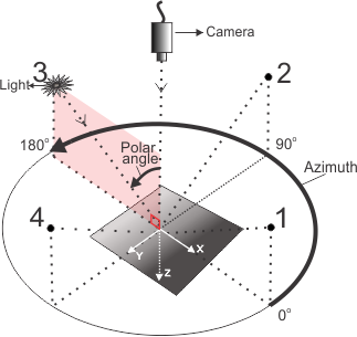
Typically, spherical coordinates are used to specify lighting positions. Use MregControl() to set the vector components for each light source with M_LIGHT_VECTOR_COMPONENT_1 for the polar (zenith) angle, M_LIGHT_VECTOR_COMPONENT_2 for the azimuth angle, and M_LIGHT_VECTOR_COMPONENT_3 for the relative light intensity, which is typically set to 1.0.
If relative light intensity is set to 1.0 for all light sources, each light provides the same intensity to the setup, which is the ideal arrangement. If equal light intensities are not possible, set the strongest light to 1.0 and set the other light intensity values relative to this.
The primary axis, used to specify the coordinates of the location of the light sources, is the vector that goes from the camera to the image. It is typical for the camera to be perpendicular to the object's surface for this application.
Remap factor
For consistent results when performing a photometric stereo operation based on shape (such as a local shape, Gaussian curvature, or mean curvature operation), you can set a remap factor. Shape-based operations are calculated using normal vectors whose magnitudes can vary widely depending on image content. Internal calculations are done in floating-point. However, to generate the photometric stereo image with the same depth as the source images, the calculated values must be mapped or scaled to integer intensity values. By default, a remap factor is automatically calculated (M_DRAW_REMAP_FACTOR_MODE set to M_DEFAULT or M_AUTO), which remaps values using the full range of values in the current image. However, with some objects and lighting, it is possible for some (but not all) source images to have peak values that are much bigger than the others in the set (for example, a random, very sharp reflection), which causes that image to use a very different remap factor, possibly diminishing important details in key parts of the image. To avoid the effect of occasional sharp transitions, you can set a constant factor to use for the remapping (M_DRAW_REMAP_FACTOR_MODE set to M_USER_DEFINED). This is useful when you are performing several shape-based operations and want to ensure that the stored results are directly comparable.
Before setting the remap factor (M_DRAW_REMAP_FACTOR_VALUE), it is recommended to find the reported automatic mode factor (using MregGetResult() with M_RANGE_FACTOR_LOCAL_SHAPE, M_RANGE_FACTOR_GAUSSIAN_CURVATURE or M_RANGE_FACTOR_MEAN_CURVATURE) for some typical images. If the resulting output is satisfactory, set M_DRAW_REMAP_FACTOR_VALUE to the automatically calculated value. If not, you can try setting the remap factor to a higher value; this increases image contrast and helps to bring out smaller details in the photometric stereo image.
Note that you can only set the remap factor when writing results to a result buffer.
Performing the photometric stereo registration operation and retrieving results
To perform the photometric stereo registration operation, call MregCalculate() with M_COMPUTE, and pass the array of input images required to generate the photometric stereo image(s) and either a destination image buffer or a photometric stereo result buffer. Subsequent calls to MregCalculate() with M_COMPUTE will clear the photometric stereo registration result buffer before storing new results if a result buffer is specified.
You can specify the photometric stereo image(s) to compute using MregControl(). These images are: local shape image, albedo image (the default setting), Gaussian curvature image, mean curvature image, local contrast image, and texture image. Each computed photometric stereo image highlights different features or surface properties of the source scene. The following are descriptions of each operation. The related images show a source image on the left and the photometric stereo result (calculated from multiple source images) on the right.
If MregCalculate() used an image buffer as the destination, you can access the resulting image immediately after the registration operation. If MregCalculate() used a result buffer as the destination, the result buffer holds the photometric stereo image(s) along with other results. You can draw the photometric stereo image(s) and/or other results into an image buffer using MregDraw(). Use MregGetResult() with M_STATUS to check if the photometric stereo image(s) is/are computed.
Example of photometric stereo on non-moving objects
The animations below illustrate what happens in the subsequent example: how surface details can be extracted with the photometric stereo registration operation. The first animation shows an M_LOCAL_SHAPE operation, revealing the raised and recessed features of the source object. The subsequent animation shows an M_DRAW_ALBEDO_IMAGE operation that detects flaws on a leather surface.


The example PhotometricStereo.cpp demonstrates several photometric stereo use cases.
Photometric stereo registration of a moving object
Typically, the scene or object undergoing photometric stereo registration is stationary. However, photometric stereo registration is possible with images taken from a moving object (for example, on a conveyor).
In the case of a moving object, the source images must be aligned before you can perform the photometric stereo registration operation. To help calculate the object's displacement, take a start and an end image with all lights on. These two images serve as anchors for locating the object in the intermediate images, which are the photometric stereo source images taken with directional lighting.
Once you have acquired the start, end, and photometric stereo source images, apply the following:
The key step for a successful photometric stereo operation on a moving object is source image alignment. Using the above method, the defined model must be visible in the start and end images. In addition, the object's displacement must be small, relative to the lighting setup, so that distinct directional lighting is maintained between each image. A small displacement also minimizes perspective distortion and parallax errors. Your application could require a different methodology (for example, to account for source object rotation).
For an illustration of photometric stereo registration on a moving object, see the following example.