Performing 3D fitting
- See also

 Availability
 Previous
- Next

-
Allocate a fit 3D metrology context, using M3dmetAlloc() with M_FIT_CONTEXT.
-
Allocate a fit 3D metrology result buffer, using M3dmetAllocResult() with M_FIT_RESULT.
-
Control the settings of the fit 3D metrology context using M3dmetControl(). These settings specify stop conditions for the fitting operation, and determine how the initial fit estimate is calculated using M_ESTIMATION_MODE.
Note that, if M_ESTIMATION_MODE is set to M_FROM_GEOMETRY, use M3dmetCopy() with M_ESTIMATE_GEOMETRY to copy a 3D geometry into the fit 3D metrology context. This geometry will then be used as the initial fit estimate. By default, the fit 3D metrology context contains an undefined geometry object, and will cause an error if you initiate the fit operation with this estimation mode.
-
Call M3dmetFit() to perform the fitting operation. In the function call, you must specify the type of 3D geometry to fit to the point cloud or depth map, and how points are determined to be outliers or inliers.
-
Retrieve results from the fit 3D metrology result buffer using M3dmetGetResult(), including the status of the fitting operation. Retrieve the fitted geometry using M3dmetCopyResult() with M_FITTED_GEOMETRY.
The MIL 3D metrology module can preform a fitting operation. The fitting operation tries to fit a specified type of 3D geometry to a point cloud or depth map. The fitting operation minimizes the average root-mean-squared (RMS) error between the 3D geometry and the inlier points of the point cloud or depth map. The RMS error is minimized over several iterations.
For a single iteration, the RMS error is only calculated for points that are considered inliers for that iteration (as specified using M3dmetFit() with the OutlierDistance parameter) to avoid fitting the specified 3D geometry to spurious points in the point cloud or depth map. Spurious points are typically caused by image noise, object deformity, or occlusion.
At the beginning of the fitting operation, an initial fit estimate is calculated (as specified using M3dmetControl() with M_ESTIMATION_MODE) to define an initial position of the 3D geometry relative to the point cloud or depth map. In the next iteration, points are defined as inliers or outliers depending on whether they are within the outlier distance from the surface of the 3D geometry. The RMS error between the geometry and inliers is calculated, and the 3D geometry is then repositioned to minimize the RMS error. This continues with each iteration, until one of the stop conditions is met.
Optionally, when performing a fitting operation with a fit 3D metrology context that has M_ESTIMATION_MODE set to M_FROM_GEOMETRY, you can specify a 3D geometry object (allocated using M3dgeoAlloc() and defined using an appropriate function from the M3dgeo...() module) to use for the first iteration. Otherwise, you do not specify a 3D geometry object for a fitting operation.
Steps to perform a fitting operation
The following steps provide a basic methodology for performing a fitting operation:
Specifying points or pixels not to use for fitting
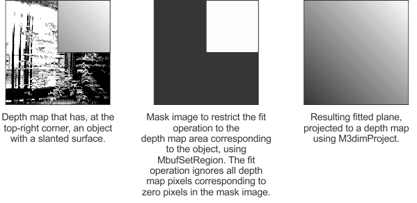
If you need to only fit to a subset of the points of a point cloud, or pixels of a depth map, you can do so by cropping a point cloud (using M3dimCrop()) or specifying a raster ROI for a depth map (using MbufSetRegion()), respectively. This is useful, for example, when there are multiple objects in the point cloud or depth map to which a 3D geometry could be fit.
For information about cropping a point cloud, see the Cropping or masking points subsection of the Working with points in a point cloud section of Chapter 32: 3D image processing.
When specifying an ROI for a depth map, note that M3dmetFit() fits the geometry to all depth map pixels inside the ROI that are not outside the specified outlier distance (OutlierDistance). Therefore, your ROI should mask out any objects or parts of objects that you do not want considered for the fit operation.
Using a fitted geometry to mask points from a point cloud
You can use a fitted geometry to specify which points to mask from a point cloud. That is, any points that the geometry was fitted to will have their confidence score set to 0, using M3dmetCopyResult() with M_OUTLIER_MASK. Once the confidence score is set to 0, these points will be excluded from analysis and processing operations. This can be useful to remove a plane from the background.
The snippet below shows how to use a fitted plane geometry to mask points from a point cloud:
// Specify a tolerance for the fitting operation
static const MIL_DOUBLE PLANE_TOLERANCE = 1.0;

// Fit a plane using default settings
MIL_ID MilFitResult = M3dmetAllocResult(MilSystem, M_FIT_RESULT, M_DEFAULT, M_NULL);
M3dmetFit(M_DEFAULT, MilPointCloud, M_PLANE, MilFitResult, PLANE_TOLERANCE, M_DEFAULT);

// Inquire the ID of the point cloud's confidence component
MIL_ID ConfidenceBuffer;
MbufInquireContainer(MilPointCloud, M_COMPONENT_CONFIDENCE, M_COMPONENT_ID, &ConfidenceBuffer);

// Copy only the points that were considered outliers during the fit operation
// into ConfidenceBuffer
M3dmetCopyResult(MilFitResult, ConfidenceBuffer, M_OUTLIER_MASK, M_DEFAULT);

M3dmetFree(MilFitResult);