Working with points in a point cloud
- See also

 Availability
 Previous
- Next

-
Play speed: Start position: Looping: - 1 of 5
-
Play speed: Start position: Looping: - 1 of 4
-
Unorganized (M_UNORGANIZED). Specifies to store results in an unorganized point cloud, removing any invalid points in the process. This option typically uses less memory, at the cost of losing organization.
-
Shrink (M_SHRINK). Specifies to copy, from source to destination, the smallest region that holds all valid points. With this option, point cloud organization is kept. This is useful when cropping a small, localized area of a larger, organized point cloud.
-
Same (M_SAME). Specifies to keep the source point cloud's organization, and to modify only the M_COMPONENT_CONFIDENCE component, invalidating the cropped points by setting their confidence to 0; all other source components are copied unchanged into the destination container. M_SAME is a fast option if cropping in place, since no separate allocation or copy operations are required. The M_SAME option is also useful if the relation to the original point positions are needed in the resulting point cloud. M_SAME is the default option.
-
Decimate mode (M_SUBSAMPLE_DECIMATE). Selects points at regular intervals (set with M_STEP_SIZE_X and M_STEP_SIZE_Y). This is the default mode and is typically used with organized point clouds. This mode is typically faster than the other modes.
The following code snippet is an example of the steps required to subsample a point cloud in decimate mode:
/* Allocate a subsample context and set it to decimate mode. */ MilSubsampleContext = M3dimAlloc(MilSystem, M_SUBSAMPLE_CONTEXT, M_DEFAULT, M_NULL); M3dimControl(MilSubsampleContext, M_SUBSAMPLE_MODE, M_SUBSAMPLE_DECIMATE); /* Set the interval size and specify to keep the organization type. */ M3dimControl(MilSubsampleContext, M_STEP_SIZE_X, DECIMATION_STEP); M3dimControl(MilSubsampleContext, M_STEP_SIZE_Y, DECIMATION_STEP); M3dimControl(MilSubsampleContext, M_ORGANIZATION_TYPE, M_ORGANIZED); /* Apply sampling. */ M3dimSample(MilSubsampleContext, MilPointCloud, MilDstPointCloud, M_DEFAULT);Note that M_SUBSAMPLE_DECIMATE can sometimes generate undesirable regular patterns. To avoid such patterns, use random mode (M_SUBSAMPLE_RANDOM) instead.
-
Random mode (M_SUBSAMPLE_RANDOM). Selects points using an operation that randomly selects a specified fraction of points from the source point cloud. Set the seed for the random number generator with M_SEED_VALUE; set the fraction with M_FRACTION_OF_POINTS.
-
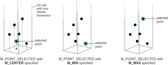
Grid mode (M_SUBSAMPLE_GRID). Selects points using a grid operation, which divides the 3D space into cells. For each cell, M3dimSample() selects one point: either the point closest to the cell's center, or the selection is determined using the mode specified with M_POINT_SELECTED. Set the cell size with M_GRID_SIZE_.... You can use grid mode to organize an unorganized point cloud (set M_ORGANIZATION_TYPE to M_ORGANIZED). Grid mode is also useful after merging point clouds (using M3dimMerge()) to ensure an approximately constant spacing between points.
The following code snippet is an example of the steps required to subsample an unorganized point cloud using the grid mode, and generate a new, organized point cloud:
static const MIL_DOUBLE GRID_SIZE = 1.0; /* Allocate a subsample context and set it to grid mode. */ MilSubsampleContext = M3dimAlloc(MilSystem, M_SUBSAMPLE_CONTEXT, M_DEFAULT, M_NULL); M3dimControl(MilSubsampleContext, M_SUBSAMPLE_MODE, M_SUBSAMPLE_GRID); /* Organize the unorganized source point cloud with resolution in X and Y equal to the grid size. */ M3dimControl(MilSubsampleContext, M_ORGANIZATION_TYPE, M_ORGANIZED); M3dimControl(MilSubsampleContext, M_GRID_SIZE_Z, M_INFINITE); M3dimControl(MilSubsampleContext, M_GRID_SIZE_X, GRID_SIZE); M3dimControl(MilSubsampleContext, M_GRID_SIZE_Y, GRID_SIZE); /* Select the point with the lowest coordinate along the M_INFINITE axis for each cell. */ M3dimControl(MilSubsampleContext, M_POINT_SELECTED, M_MIN); /* Apply sampling. */ M3dimSample(MilSubsampleContext, MilPointCloud, MilDstPointCloud, M_DEFAULT);Note that, when M_ORGANIZATION_TYPE is set to M_ORGANIZED, exactly 1 of M_GRID_SIZE_X, M_GRID_SIZE_Y, or M_GRID_SIZE_Z must be set to M_INFINITE. When M_ORGANIZATION_TYPE is set to M_UNORGANIZED, you can set at most 1 of M_GRID_SIZE_... to M_INFINITE.
When one of M_GRID_SIZE_... is set to M_INFINITE, the point selected for a cell depends on the mode specified with M_POINT_SELECTED, which is, by default, the highest point along the M_INFINITE axis (M_MAX). When none of M_GRID_SIZE_... is set to M_INFINITE, the point selected for a cell is the point closest to the cell's volumetric center.
The following image shows options for the M_POINT_SELECTED control type. Note that the M_CENTER option selects the point closest to the center of each 2D cell, as if the point cloud is collapsed onto the plane formed by the 2 non-infinite dimensions.
-
Normal mode (M_SUBSAMPLE_NORMAL). Selects points based on normal vector angles and neighborhood distance (set with M_DISTINCT_ANGLE_DIFFERENCE and M_NEIGHBORHOOD_DISTANCE). This mode is best used when compressing the source point cloud. Points around key features like corners and edges are kept, while the number of points on flat surfaces is reduced.
The following image shows the result of using the normal mode with M_DISTINCT_ANGLE_DIFFERENCE and M_NEIGHBORHOOD_DISTANCE.
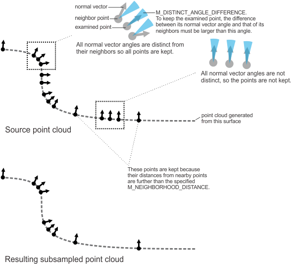
The following code snippet is an example of the steps required to subsample a point cloud in normal mode. Note the specified M_DISTINCT_ANGLE_DIFFERENCE and M_NEIGHBORHOOD_DISTANCE values. The 12 degree distinct angle difference specifies that the point is kept if all neighboring points' normal vectors differ by more than 12 degrees from the examined point's normal vector angle. The neighborhood within which to consider the normal vector of surrounding points is limited to 10 world units from the examined point.
/* Allocate a subsample context and set it to normal vector mode. */ MilSubsampleContext = M3dimAlloc(MilSystem, M_SUBSAMPLE_CONTEXT, M_DEFAULT, M_NULL); M3dimControl(MilSubsampleContext, M_SUBSAMPLE_MODE, M_SUBSAMPLE_NORMAL); /* Control what makes a point distinct from its neighbors. */ M3dimControl(MilSubsampleContext, M_DISTINCT_ANGLE_DIFFERENCE, 12); M3dimControl(MilSubsampleContext, M_NEIGHBORHOOD_DISTANCE, 10); /* Apply sampling. */ M3dimSample(MilSubsampleContext, MilPointCloud, MilDstPointCloud, M_DEFAULT);
Beyond moving or scaling the coordinates of existing points in a point cloud (see the Moving or scaling a point cloud or 3D geometry section earlier in this chapter), you can crop or mask points, merge point clouds, or construct a meshed surface for a point cloud. You can also sample points to reduce the number of points (subsampling) or, for a meshed point cloud, increase the number of points (surface sampling).
Cropping or masking points
To crop or mask points in a point cloud, use M3dimCrop(). You can crop using a specified 3D geometry object, or mask points using an image buffer. In the mask case, points are projected onto the mask image and, if the corresponding pixel is 0-valued, the point is not kept.
Cropping using a 3D geometry
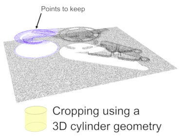
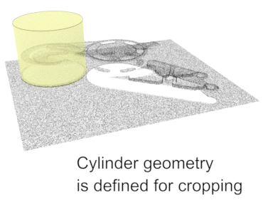
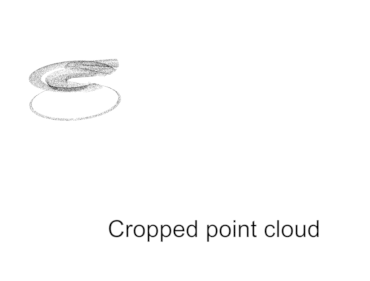
When cropping using a 3D geometry, you can use a closed geometry to define a region in 3D space. Points inside the region are kept; points outside the region are cropped out. Specify M_INVERSE to reverse which points are kept.
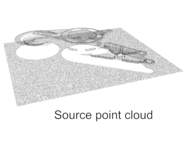
The following animation shows cropping using a 3D cylinder geometry.

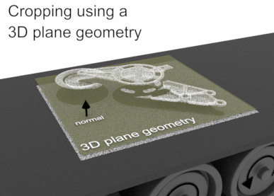
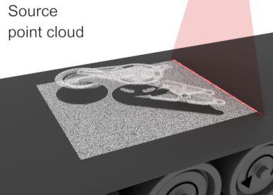
You can crop using a plane geometry. By definition, points on one side of the plane are kept, and points on the other side are cropped out. Specify M_INVERSE to reverse which points are kept. Note that the direction of the plane's normal vector determines the default side for which points are kept.
The following animation shows cropping using a 3D plane geometry.

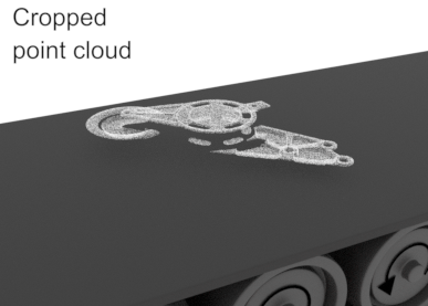
Cropping using a mask image
You can crop using a mask image, where pixels with a 0 value determine points to crop, after projection onto the mask image buffer. The following image shows cropping using a uniformly-calibrated mask image.
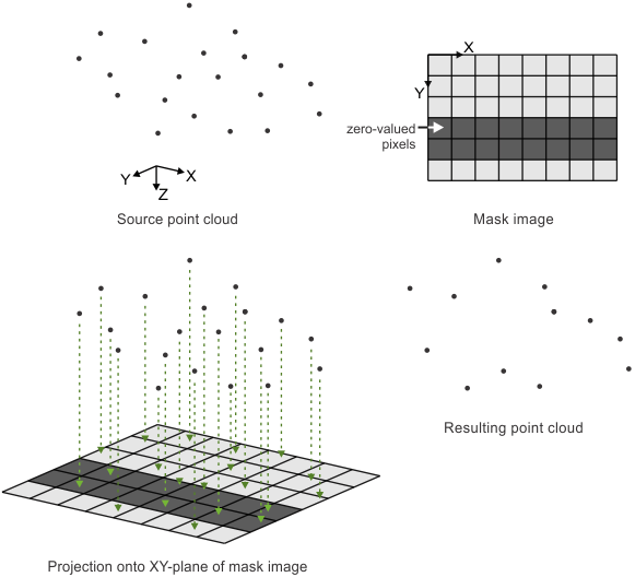
With a uniformly-calibrated image mask, M3dimCrop() projects points orthogonally onto the mask, which means that points are projected parallel to the Z-axis, onto the XY-plane. To create such a mask, you can start by generating a depth map of the point cloud using M3dimProject(). You can use the Model Finder module to locate the target object in the resulting depth map, and then clear to 0 unwanted pixels as required. You can also use a graphical user interface to interactively block out or mask areas in the depth map image, before passing the mask image to M3dimCrop().
You can also crop using a 3D-calibrated image mask. In this case, M3dimCrop() projects points along paths that follow the frustum of the camera's view (instead of orthogonally), as represented by the mask image's associated camera calibration information. To do so, use an image of the scene that is associated with a camera calibration of type M_TSAI_BASED or M_3D_ROBOTICS. This is useful when selecting points using a graphical user interface, where you can select or block out points on screen, thereby defining the mask image. Since the camera image is 3D-calibrated, the region selected from the display specifies points within a 3D volume. To apply the crop, pass the calibrated mask image buffer to M3dimCrop().
Specifying the organization type
When calling M3dimCrop(), you can specify how to organize the resulting point cloud. The following settings are available:
For information on point cloud organization, see the Organized and unorganized point clouds subsection of this section.
Defining which points to use
When working with a point cloud, you can typically specify whether to use a 3D box geometry object to delimit which points to use for processing and analysis operations. You can also remove invalid points. By default, all valid points are used.

You can define the size of the 3D box geometry by specifying coordinates and/or dimensions, such as X, Y, or Z lengths. See the Steps to defining and using a 3D geometry object subsection of the Defining 3D geometries section of Chapter 38: Using the 3D Geometry module for more information. Alternatively, you can use 3D box geometry results from other modules.
The following code snippet is an example of the steps required to generate a fully corrected depth map in a box region of a point cloud:
/* Crop the point cloud. */
M3dimCrop(MilPointCloud, MilCroppedPointCloud, MilBox, M_NULL, M_DEFAULT, M_DEFAULT);
M3dimCalibrateDepthMap(MilBox, MilDepthmap, M_NULL, M_NULL, M_DEFAULT, M_POSITIVE, M_DEFAULT);

/* Project the point cloud on the depth map. */
M3dimProject(MilCroppedPointCloud, MilDepthmap, M_NULL, M_POINT_BASED, M_MAX_Z, M_DEFAULT, M_DEFAULT);
Specifying a bounding box excluding outliers
To exclude outliers, you can use M3dimStat() to calculate the bounding box of a point cloud excluding outliers. In this case, M3dimStat() calculates the smallest axis-aligned box that contains all the valid points in a point cloud except those suspected to be outliers. You can then copy the resulting bounding box into a 3D box geometry, using M3dimCopyResult() with M_BOUNDING_BOX. For more information, see the Determining the bounding box of a point cloud subsection of the Calculating statistics on a point cloud or depth map section later in this chapter.
Specifying the extent box
To include only points in the maximum area that a depth map can span given the image buffer size and the calibration information of that buffer, you can copy the depth map's extent box into a 3D geometry object. In this case, the resulting 3D box geometry's dimensions are calculated to represent this maximum area. To do so, use M3dimCopy() with M_EXTENT_BOX. M3dimCopy() uses the following information from the depth map: the position of the origin of the pixel coordinate system in the relative coordinate system, the three dimensional scales (M_PIXEL_SIZE_X, M_PIXEL_SIZE_Y, and M_GRAY_LEVEL_SIZE_Z), and the dimensions of the depth map image buffer.
Removing invalid points
You can remove invalid points from a point cloud. For example, if you require only valid points for a processing operation, you can call M3dimRemovePoints() to remove invalid points from the point cloud before calling, for example, MbufGet(), which will then retrieve only valid points. Note that, when using M3dimRemovePoints(), the resulting point cloud is always unorganized.
To remove points whose confidence is equal to zero, use M3dimRemovePoints() with M_INVALID_POINTS_ONLY. To remove both these points and points whose normal vector values are zero, use M_INVALID_NORMALS instead.
The following code snippet is an example of the steps required to get only valid points from a container:
std::vector<MIL_FLOAT> X;
std::vector<MIL_FLOAT> Y;
std::vector<MIL_FLOAT> Z;

/* Remove invalid points. */
M3dimRemovePoints(MilPointCloud, MilDstPointCloud, M_INVALID_POINTS_ONLY, M_DEFAULT);

/* Retrieve the coordinates of remaining points. */
MIL_ID RangeId = MbufInquireContainer(MilDstPointCloud, M_COMPONENT_RANGE, M_COMPONENT_ID, M_NULL);
MbufGetColor(RangeId, M_SINGLE_BAND, 0, X);
MbufGetColor(RangeId, M_SINGLE_BAND, 1, Y);
MbufGetColor(RangeId, M_SINGLE_BAND, 2, Z);
Merging point clouds
You can use M3dimMerge() to combine multiple point clouds into a single point cloud. The function assumes the working coordinate systems of the point clouds are aligned. Optionally, you can pass M3dimMerge() a subsample context (discussed below) when merging, to reduce the number of points in the resulting point cloud. Note that, if you pass a subsample context that specifies an organized destination point cloud, the resulting merged point cloud will be organized. Without such a context, the resulting point cloud is always unorganized when using M3dimMerge(). For information on point cloud organization, see the Organized and unorganized point clouds subsection of this section.
To align the working coordinate systems of multiple point clouds and then merge, use M3dregMerge() instead. See the Merging point clouds and retrieving registration results section of Chapter 34: 3D registration for more information.
Calculating unit normal vectors
You can calculate each point's unit normal vector, which is a vector perpendicular to a surface estimated from the positions of surrounding points. Normal vectors are useful, for example, when reconstructing a surface for the point cloud (M3dimMesh()), or for registration operations using the 3D Registration module. To calculate the normal vectors, use M3dimNormals(). This function stores the unit normal vector of each point in the normals component of the operation's destination container, creating or reallocating the component if necessary. Note that, to increase calculation speed, M3dimNormals() can use either existing organizational information in the point cloud or a mesh component.
Surface reconstruction
You can generate a mesh for a point cloud, which is a reconstructed triangulated surface. Use M3dimMesh(). This function generates a mesh according to the specified mesh 3D image processing context (M3dimAlloc() with M_MESH_CONTEXT). Use M3dimControl() to set up the context. Choose the reconstruction mode (M_MESH_MODE) with which to create the mesh, either organized or smoothed. The organized mode connects existing points according to organizational information, and can result in a mesh with holes, due to invalid points in the source point cloud. With the smoothed mode, a normals component is required, and the resulting mesh is without holes. Note that when using the smoothed mode, there will probably be more points in the resulting point cloud and the points will probably not be the same as that of the source point cloud. M3dimMesh() stores the generated mesh in the mesh component of the destination container.
Sampling a point cloud
You can use the M3dimSample() function to reduce the number of points in a point cloud (subsampling), or increase the number of points in a meshed point cloud (surface sampling). Subsampling is useful, for example, to maintain an approximately similar distance between points after a merge operation, or when compressing point cloud data. You can also subsample an unorganized point cloud to obtain an organized point cloud.
Subsampling
To subsample, allocate a subsample 3D image processing context using M3dimAlloc() with M_SUBSAMPLE_CONTEXT and set the type of subsampling operation to perform using M3dimControl() with M_SUBSAMPLE_MODE. Choose from the following modes:
Note that you can specify the organizational type of the resulting point cloud (M_ORGANIZATION_TYPE). An M_ORGANIZED output point cloud is available only for M_SUBSAMPLE_DECIMATE or M_SUBSAMPLE_GRID operations. When M_ORGANIZATION_TYPE is set to M_UNORGANIZED, invalid points are removed.
For information on point cloud organization, see the Organized and unorganized point clouds subsection of this section.
Surface sampling
You can use M3dimSample() to surface sample a meshed point cloud and generate a denser (non-meshed) point cloud. This is useful, for example, when performing 3D registration with an acquired point cloud and a CAD model. A point cloud restored from a CAD file is often sparse, with large surface triangles on flat surfaces. You can apply a surface sample operation to the CAD-sourced point cloud to increase its density and subsequently improve registration results, since both point clouds should have a similar point density. Note that you can use MbufImport() or MbufRestore() to import/restore an acquired point cloud or a CAD file.
To perform surface sampling, use M3dimSample() with a surface sample 3D image processing context, allocated using M3dimAlloc() with M_SURFACE_SAMPLE_CONTEXT. A M_COMPONENT_MESH_MIL component must exist in the source point cloud. Use M3dimControl() with M_RESOLUTION to control the density of newly added points. M3dimSample() samples the surface, and places a denser (non-meshed) point cloud into the destination container.

Organized and unorganized point clouds
A point cloud can be organized or unorganized. In an organized point cloud, points close to each other in 3D space are stored close to each other in the pixel coordinate systems of the components. Typically, you can ignore whether a point cloud is organized; most operations are supported for both organized and unorganized point clouds. However, in some cases, you can improve performance with an organized or unorganized point cloud.
You can determine if a point cloud is organized using MbufInquireContainer() with M_COMPONENT_RANGE and M_3D_REPRESENTATION. If the returned value is M_CALIBRATED_XYZ_UNORGANIZED, the point cloud is unorganized; otherwise, it is organized.
Setting the 3D representation of a range component to indicate that it is organized when the underlying data is unorganized can lead to unexpected results.
Some operations have modes that can only be specified for an organized point cloud. For example, for a normals 3D image processing context, you can use M3dimControl() with M_NEIGHBOR_SEARCH_MODE set to M_ORGANIZED. In this case, M3dimNormals() will use the organization of the point cloud to calculate the normals more efficiently.
Modes specific to organized point clouds are not available when the range component is a buffer with a single row (M_SIZE_Y is equal to 1), even if the data is organized.
If you have an organized point cloud with a large number of invalid points, it might be more efficient to convert it to an unorganized point cloud with only valid points (using M3dimRemovePoints()). This reduces the memory required to store the point cloud, and improves the performance of some operations. Typically, this will only improve the performance of your application if you need to perform multiple operations with the same point cloud.
Typically, 3D data grabbed from a 3D sensor is organized. A point cloud converted from a depth map using MbufConvert3d() is always organized. You can create an organized point cloud that has a subset of the points of an unorganized point cloud by subsampling it using M3dimSample() with a subsample 3D image processing context that specifies a M_SUBSAMPLE_GRID operation and an M_ORGANIZED organization type.