3D coordinate systems and the coordinates of a point cloud
- See also

 Availability
 Previous
- Next

-
Its X-axis and origin are on the intersection of the laser plane and the conveyor (laser line).
-
Its Y-axis is parallel to the object's motion.
-
Its Z-axis is perpendicular to the plane of the conveyor and points in the direction of the absolute coordinate system's Z-axis. The XY-plane of the absolute coordinate system must be parallel to the conveyor as well.
Note that if the Z-axis points down, the Z-coordinate decreases in the direction in which height of the objects increase. This leads to negative Z-coordinates for scanned objects.
-
The origin and the direction of the X-axis and Y-axis are as close to the absolute coordinate system as possible, given the above constraints.
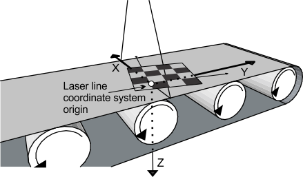
Once a 3D reconstruction setup has been calibrated using M3dmapCalibrate() (or M3dmapCalibrateMultiple() in the case of multiple camera-laser pairs discussed later), a new coordinate system is created in the 3D reconstruction context: the laser line coordinate system. This coordinate system is a real-world coordinate system partially defined by the intersection of the laser plane with the conveyor (the laser line).
Once you allocate a result buffer using M3dmapAllocResult() with M_POINT_CLOUD_RESULT, another new coordinate system is created in the 3D reconstruction result buffer: the relative coordinate system of the 3D result buffer. Once you add 3D data to the result buffer using M3dmapAddScan(), this relative coordinate system overlaps the laser line coordinate system.
The relative coordinate system in the result buffer can be moved, while the laser line coordinate system in the context is always fixed. All results are returned with respect to the relative coordinate system.
Understanding the laser line coordinate system
The laser line coordinate system is the coordinate system used to represent 3D points generated by the 3D Reconstruction module. It is defined in the 3D reconstruction context upon calling M3dmapCalibrate() or M3dmapCalibrateMultiple().
The laser line coordinate system has the following characteristics:
In the image below, the absolute coordinate system, which was previously defined using the chessboard grid shown, is not aligned with the conveyor or the laser line. The laser line coordinate system, however, must be aligned with the direction of the conveyor and laser line. So in the laser line coordinate system, the direction of the Y-axis is close to the direction of the absolute coordinate system's Y-axis, but is still parallel with the movement of the conveyor. This direction is essential to understanding why the Y-coordinates of points of an object will increase or decrease as the object moves on the conveyor.
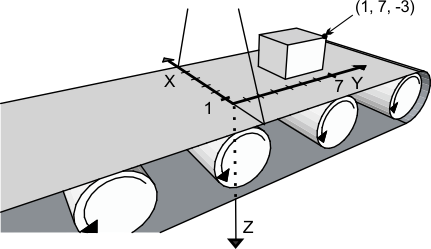
By default, an object's coordinates are initially based on the position of the object in the laser line coordinate system at the moment of the first call to M3dmapAddScan(). Despite the object actually moving along the conveyor to pass under the laser line, the result buffer stores the object's coordinates as they were before the first scan. In the image below, the object is shown in its original position, just before the first scan. Note that the first few scans in the image below will not contain any data about the object; the first few scans are of the conveyor.
All 3D coordinates are returned in the relative coordinate system of the 3D reconstruction result buffer, which is identical to the laser line coordinate system, by default.
Understanding the relative coordinate system in a 3D result buffer
The relative coordinate system in an M_POINT_CLOUD_RESULT 3D reconstruction result buffer is the coordinate system used by default when retrieving coordinates of the points in the point cloud. It is defined in an M_POINT_CLOUD_RESULT 3D reconstruction result buffer as soon as 3D data is added to a point cloud, using M3dmapAddScan().
While the coordinates of the points are created with respect to the laser line coordinate system, the coordinates are retrieved with respect to the relative coordinate system. When you create a point cloud using M3dmapAddScan(), the relative coordinate system overlaps with the laser line coordinate system.
Retrieving the coordinates of the points in a point cloud
To retrieve the coordinates of the points in a point cloud, copy the point cloud(s) to a container using M3dmapCopyResult(), then use MbufInquireContainer() to retrieve the identifier of the point cloud container's range component (M_COMPONENT_RANGE). Finally, use MbufGetColor() to place the coordinates into an array, either with three separate calls to MbufGetColor() with M_SINGLE_BAND, or with one call to MbufGetColor() with M_PACKED or M_PLANAR. Note that MbufGetColor() does not consider the container's confidence component; invalid point values are also returned.
You can similarly retrieve the intensities associated with the points, if the source container has an intensity or reflectance component.
Transforming the relative coordinate system
The coordinates of the points are expressed with respect to the relative coordinate system of the M_POINT_CLOUD_RESULT result buffer. The relative coordinate system initially overlaps with the laser line coordinate system, but while the laser line coordinate system is fixed, the relative coordinate system can be transformed. If you transform the relative coordinate system (for example, using McalSetCoordinateSystem() or McalFixture()), the returned coordinates and any other result will reflect this transformed coordinate system. Note that this would affect M3dmapCopyResult().
Results displacement mode
It can be useful to know the exact position of an object as it moves along a conveyor, for instance when generating a depth map that will be used in a pick and place application. To do this, you can use M3dmapControl() with M_RESULTS_DISPLACEMENT_MODE set to M_CURRENT. This adds the Y-axis displacement (ongoing conveyor movement) to all returned coordinates. This effectively returns the real-time position of the object, in the relative coordinate system of the result buffer, at the moment you call M3dmapCopyResult() with M_POINT_CLOUD.
The results displacement mode determines whether an object's stored coordinates are returned fixed as they were before being scanned, or as they currently are after moving along the conveyor. For example in the image below, when M3dmapControl() with M_RESULTS_DISPLACEMENT_MODE is set to M_FIXED, the coordinates of the specified point on the box before being scanned at t0 are (3, 3, -2). Regardless of the ongoing movement of the object at t1 , all results are returned as though the object was fixed at its original position. The specified point still has the same coordinates, (3, 3, -2).
When M_RESULTS_DISPLACEMENT_MODE is set to M_CURRENT, the specified point that started moving at t0 changes to (3, -8, -2) at t1 . The change in the Y-coordinate from 3 to -8 is because the conveyor moved 11 units in the direction of the negative Y-axis since the scanning began. You can determine the distance that the object traveled along the conveyor since scanning began (the change in the Y-coordinate) using M3dmapGetResult() set to M_TOTAL_DISPLACEMENT_Y.
