Using 3D cameras that output uncorrected depth maps
- See also

 Availability
 Previous
- Next

-
M is the number of internal images taken containing the laser line. One image generates one row of data, where image m corresponds to row m in the uncorrected depth map (0 <= m <= M - 1).
-
N is the X-size, in pixels, of the laser line images. One pixel corresponds to one column of data, where the pixel distance of the laser line in column n of the laser line image, corresponds to the pixel value in column n in the uncorrected depth map (0 <= n <= N - 1).
-
M is the number of internal images taken containing the laser line. One image generates one row of data, where image m corresponds to row m in the uncorrected depth map (0 <= m <= M - 1).
-
N is the Y-size, in pixels, of the laser line images. One pixel corresponds to one row of data, where the pixel distance of the laser line in row n of the laser line image corresponds to the pixel in column n in the uncorrected depth map (0 <= n <= N - 1).
The 3D Reconstruction module provides support for 3D cameras that perform laser line extraction on-board and output an uncorrected depth map. You can use the 3D reconstruction module to convert this data into a point cloud. However, to use the 3D Reconstruction module, you must reformat the uncorrected depth map to the input format of M3dmapAddScan(). You must then call M3dmapAddScan() with M_LINE_ALREADY_EXTRACTED and the reformatted uncorrected depth map. You can find examples of how this can be accomplished by following the MIL Processing Examples link in the MIL Control Center and looking under the CameraLaser3d directory.
Some 3D sensors (including some laser profilers) perform all steps of 3D reconstruction on-board and transmit 3D data in the form of a precalibrated point cloud or depth map. If you have one of these devices, you do not need to use MIL to perform laser line profiling. This section only applies to data grabbed from cameras that perform laser-line extraction (but not calibration) on-board. For information on grabbing from 3D sensors that perform all steps of 3D reconstruction on-board, see the Grabbing from 3D sensors overview section of Chapter 36: Grabbing from 3D sensors.
M3dmapAddScan() with M_LINE_ALREADY_EXTRACTED also supports uncorrected depth maps obtained using other means, provided they are in a supported format. This might be useful if any preprocessing or postprocessing is necessary during laser line extraction. For example, you can use the MimLocatePeak1d() function to create the uncorrected depth map. This function has an output format compatible with the input format of M3dmapAddScan(), so no manipulation of the data is necessary. For information on how to use the MimLocatePeak1d() function to create an uncorrected depth map, see the Peak intensity detection and depth maps section of Chapter 5: Specialized image processing.
Calibrating a 3D reconstruction setup that uses a 3D camera
Even when using a 3D camera that performs laser line extraction, you must calibrate your 3D reconstruction setup as described in the Calibrating your 3D reconstruction setup to create a point cloud section earlier in this chapter. In this case, you should not pass an entire uncorrected depth map to M3dmapAddScan(). Instead, for each gray value/height to use for calibration, you should only pass the uncorrected depth map row that corresponds to the laser line at the specified height (M3dmapControl() with M_CORRECTED_DEPTH); you must pass the row in a 1D image buffer (created, for example, using MbufAlloc1d()).
Laser data format
If the laser line data is extracted without making use of the 3D Reconstruction module, you must specify the format of the uncorrected depth map using M3dmapControl() and MimControl().
You must specify the number of bits used for the fractional part of each pixel's gray value in the resulting uncorrected depth map, using M3dmapControl() with M_EXTRACTION_FIXED_POINT control type. For example, if the gray value 47 (101111 in binary) must be interpreted as 23.5 (10111.1), you will need to set M_EXTRACTION_FIXED_POINT to 1.
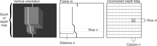
You must also specify the scan lane direction of the laser line in the camera's field of view, using MimControl() with M_SCAN_LANE_DIRECTION. Essentially, you must specify the orientation of the laser line in the internal images that the camera takes to generate the depth map. You can select either M_VERTICAL, if the images contain a horizontal laser line, or M_HORIZONTAL, if the images contain a vertical laser line.
If the M_SCAN_LANE_DIRECTION control type is set to M_VERTICAL, the uncorrected depth map must contain M rows and N columns, where:
Each entry (m, n) in the uncorrected depth map must contain a value d, which is the vertical distance of the laser line in column n of the laser line image m.
Note that the data d should be stored in the uncorrected depth map as a pixel with a gray level value bit-shifted left by the number of times equal to the value of M_EXTRACTION_FIXED_POINT. For example, if M_EXTRACTION_FIXED_POINT is set to 1, 23.5 (10111.1 in binary) should be stored as 47 (101111 in binary).
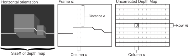
If the M_SCAN_LANE_DIRECTION control type is set to M_HORIZONTAL, the uncorrected depth map must contain M rows and N columns, where:
Each entry (m, n) in the uncorrected depth map must contain a value d, which is the horizontal distance of the laser line at row n in the laser line image m.
Note that while the orientation of the laser line in the image changes in this mode, the orientation of the uncorrected depth map does not. Consequently, row n of pixels in the laser line images actually corresponds to column n in the uncorrected depth map. This fact is illustrated in the following image.