Coordinate systems
- See also

 Availability
 Previous
- Next

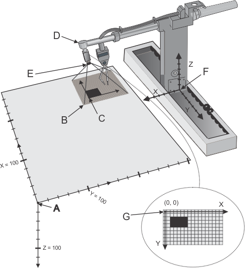
MIL supports different coordinate systems to describe positions in your camera setup. The following diagram shows these coordinate systems using a sample camera setup. Notice that the tool's position is assigned to the arm of the robotic manipulator. The Z-axis for these 3D coordinate systems follow the right-hand rule; with the thumb, index, and middle fingers of your right hand at right angles to each other, the middle finger points in the direction of the positive Z-axis when the thumb represents positive X-axis and the index finger represents positive Y-axis.
|
Legend |
||
|
Label |
Description |
Coordinates (as measured in the absolute coordinate system) |
|
A |
Origin of the absolute coordinate system. |
(0, 0, 0) |
|
B |
Camera field of view from which image is captured |
(180, 130, 0) |
|
C |
Origin of the relative coordinate system |
(190, 145, 0) |
|
D |
Origin of the tool coordinate system |
(190, 155, -75) |
|
E |
Origin of the camera coordinate system |
(190, 155, -60) |
|
F |
Origin of robot-base coordinate system |
(160, 360, -20) |
|
G |
Pixel coordinate system |
- |
Absolute world coordinate system
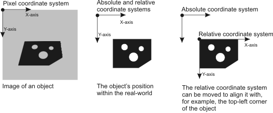
The absolute world coordinate system is implicitly defined from the calibration points when calibrating the camera setup. The absolute world coordinate system is unmovable. Its unit of measure is user-defined (for example, mm, cm, or inches). Calibration relates the pixel coordinate system to the absolute world coordinate system.
For the sake of simplicity, the absolute world coordinate system will be known as the absolute coordinate system.
Relative world coordinate system
The relative world coordinate system is the coordinate system used to locate and/or measure objects in the real world. By default, after calibration, positional results will be returned with respect to the relative world coordinate system, rather than the pixel coordinate system. Initially, the relative world coordinate system has the same position and orientation as the absolute coordinate system. However, to get results relative to some object, the relative coordinate system can be moved anywhere within the absolute coordinate system and rotated by any angle. Its unit of measure is the same as the absolute coordinate system. For the sake of simplicity, the relative world coordinate system will be known as the relative coordinate system.
Tool coordinate system
The tool coordinate system relates to the tool that holds the camera in your camera setup. For example, in a robotic arm application, the origin of the tool coordinate system would be the end point of the tool's arm holding the camera. By default, the tool coordinate system has the same position and orientation as the absolute coordinate system.
The tool position can be any arbitrary point that moves with the camera. Moving the origin of the tool coordinate system is an indirect means of positioning the camera coordinate system. Since moving the camera coordinate system implies a different field of view, moving the origin of the tool coordinate system affects positional results taken from a calibrated image. The world coordinates of an image pixel taken before and after moving the tool coordinate system are not the same.
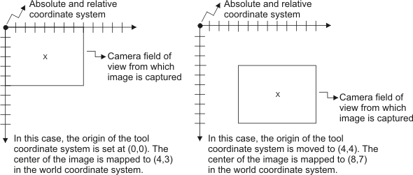
Adjusting the tool position can be useful when analyzing an object that cannot fit in a single image. For more information, see the Calibrating a camera setup that analyzes large objects section later in this chapter.
Camera coordinate system
The camera coordinate system is the coordinate system with an origin positioned at the center of the camera's lens and is only useful for 3D camera calibration modes. Its X-axis is oriented towards the right of the image, its Y-axis is oriented downwards in the image, and its Z-axis is oriented in the direction the camera is pointing (into the image). The 2D camera calibration modes do not estimate the position of the camera coordinate system; the movement of the camera coordinate system is accomplished by moving the tool coordinate system. The 3D camera calibration modes estimate the orientation and distance between the camera and the camera calibration plane as part of their algorithmic calculations; so when using this mode, the camera position is the position of the modeled pinhole camera calculated using Tsai-based algorithm.
Moving the camera coordinate system is usually performed by moving the tool coordinate system. See the Moving coordinate systems to reflect camera setup changes section later in this chapter for more information on moving your camera. Moving the origin of the camera coordinate system affects positional results taken from a calibrated image. The world coordinates of an image pixel taken before and after moving the camera coordinate system are not the same.
Robot-base coordinate system
The robot-base coordinate system is the coordinate system with an origin positioned at the base of the robot holding the camera. It is used by the robot software to allow setting the tool coordinate system with respect to the robot's base and can be used to provide the camera calibration module with values returned by the robot encoder. This coordinate system is only available for robotics camera calibration modes.
The robot base coordinate system simplifies defining the tool coordinate system. Even if its position and orientation with respect to the absolute coordinate system is originally unknown, the tool coordinate system can still be defined with respect to the robot base coordinate system. After performing full calibration, the relation between the robot base coordinate system and absolute coordinate system is established, as well as the relation between tool and absolute coordinate systems.
Usually, you cannot move the robot-base coordinate system, unless the robotic encoders are set on a mobile robot base.
Pixel coordinate system
The pixel coordinate system is the coordinate system used to locate and/or measure objects in a non-calibrated image. Its unit of measure is pixels. Its origin, (0, 0), is the center of the image's top-left pixel. Its X-axis follows the first row of pixels, pointing to the right and the Y-axis follows the first column of pixels downwards. For more information, see the Pixel conventions and subpixel accuracy section of Chapter 21: Data buffers.