Moving coordinate systems to reflect camera setup changes
- See also

 Availability
 Previous
- Next

-
Specify an exact transformation using McalSetCoordinateSystem() for 3D-based camera calibration contexts (M_TSAI_BASED or M_3D_ROBOTICS) or using McalRelativeOrigin() or McalControl() for other camera calibration contexts.
-
Automatically recalculate the camera coordinate system's new postion using McalGrid() or McalList() for 3D-based camera calibration contexts (M_TSAI_BASED or M_3D_ROBOTICS).
-
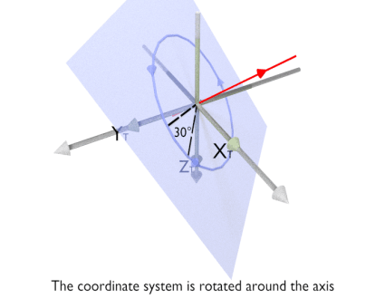
Axis and angle rotation. Expresses the rotation of the target coordinate system as a rotation of all its points by a certain angle of rotation (
 ), around an
arbitrary axis of rotation defined by a unit vector in the
reference coordinate system.
), around an
arbitrary axis of rotation defined by a unit vector in the
reference coordinate system.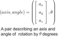
The animation below illustrates rotation using McalSetCoordinateSystem() with M_ROTATION_AXIS_ANGLE and M_ASSIGN.
-
Quaternion rotation. Expresses the rotation of the target coordinate system as a quaternion from the angle of rotation (
) and the
normalized axis of rotation (  ), as defined in the following
equation.
), as defined in the following
equation.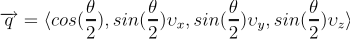
-
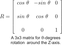
Matrix rotation. Expresses the rotation of the target coordinate system as a 3x3 square matrix transformation.
-
X-Y-Z rotation. Expresses the rotation of the target coordinate system as a rotation of all points along the three axes of the reference coordinate system, with all possible X-, Y- and Z-component combinations. It is also known as Roll-Pitch-Yaw rotation.
The animation below illustrates the rotation using McalSetCoordinateSystem() with M_ROTATION_XYZ and M_ASSIGN.


-
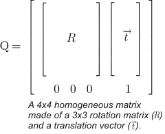
Homogeneous matrix rotation. Expresses the rotation of the target coordinate system as a homogeneous matrix transformation. Homogeneous matrices can express both a translation and a rotation of a coordinate system. It is a 4x4 matrix made up of a 3x3 rotation matrix and a translation vector. If the rotation matrix is an identity matrix, only a translation takes effect.
-
To define, move, or rotate the relative coordinate system, use McalRelativeOrigin().
-
To specify a new position for the tool coordinate system, you can use McalControl() with M_TOOL_POSITION_X, M_TOOL_POSITION_Y, and M_TOOL_POSITION_Z.
-
From the origin and orientation of the reference coordinate system, using McalSetCoordinateSystem() with M_ASSIGN. This method is useful to explicitly define the origin of the relative coordinate system or the tool coordinate system when they have not been previously defined. It is also useful when, for example, all movements of the target coordinate system are only known from the origin of the reference coordinate system.
-
From its current position in a reference coordinate system using M_COMPOSE_WITH_CURRENT. The transformation is still defined in terms of the reference coordinate system. Essentially, the specified transformation is composed with the current position and orientation of the target coordinate system. This method is useful, for example, to translate the tool coordinate system, when you know the precise movement of a robotic arm in the absolute coordinate system.
Once your camera setup is calibrated, you might need to reposition the world coordinate systems, established during calibration, for different reasons. For example, you might need to reposition the tool and the camera coordinate system because the tool holding your camera might have moved, or you might need to reposition the relative coordinate system to measure, in real-world units, an object located at a different position in an image (fixturing).
There are two general ways to reposition a coordinate system:
All results are returned with respect to the relative coordinate system, so you must ensure it is placed at an appropriate location for your measurements. If you are using 3D-based camera calibration modes, the location of the relative coordinate system along the Z-axis of the absolute coordinate system also affects measurements. For more information, see the Moving the relative coordinate system to account for height section of Chapter 31: 3D analysis using planar views of an object.
Types of transformation
MIL can reposition a coordinate system (target) with respect to another coordinate system (reference), using two main types of transformations: translation and rotation.
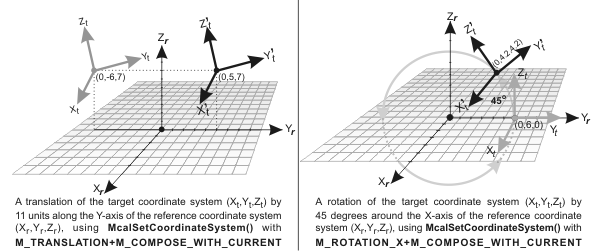
Translation
A translation of a coordinate system is equivalent to the displacement of all points along the reference coordinate axes and is specified using a translation vector. For camera calibration contexts using a perspective-transformation mode or linear-interpolation mode (two-dimensional camera calibration modes), you can move the relative coordinate system using McalRelativeOrigin(). For 3D-based camera calibration contexts, you can apply a translation along the X, Y, and Z-axes using McalSetCoordinateSystem() with M_TRANSLATION.
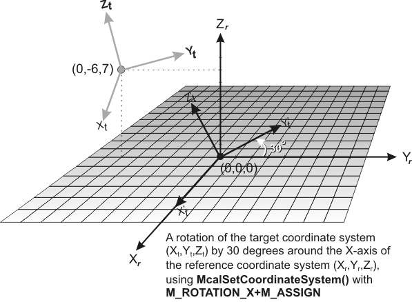
Rotation
A rotation of a coordinate system is equivalent to the movement of all points in a circular motion around some axis in a reference coordinate system.
To rotate the relative coordinate system of a camera calibration context that uses a two-dimensional camera calibration mode, use McalRelativeOrigin() with the AngularOffset parameter set to the rotation angle, in degrees.
To rotate a coordinate system of a 3D-based camera calibration context, use McalSetCoordinateSystem(). Rotations in three-dimensional space can be specified in multiple ways using this function:
Transforming coordinate systems
For two-dimensional camera calibration modes, you can only transform the relative and tool coordinate systems.
For three-dimensional camera calibration modes, use McalSetCoordinateSystem() to transform a three-dimensional coordinate system in terms of another. This function can apply the transformation of a specified target coordinate system in two distinct ways:
Note that the pixel coordinate system cannot be used with McalSetCoordinateSystem().
The following code snippet shows how to use McalSetCoordinateSystem() to update your camera calibration context after rotating a robotic arm by 30 degrees. The robotic arm is the tool holding the camera; this means that the tool coordinate system should be rotated. Note that this will also rotate the camera if M_LINK_TOOL_AND_CAMERA is set to M_ENABLE, which is the default behavior.
/*
*   A robotic arm is holding the camera.
*   The arm rolls 30 degrees around its own axis (the Z axis)
*/

McalSetCoordinateSystem(CalibrationId, M_TOOL_COORDINATE_SYSTEM, M_TOOL_COORDINATE_SYSTEM,
                  M_ROTATION_Z + M_COMPOSE_WITH_CURRENT, M_NULL, 30.0,
                  M_DEFAULT, M_DEFAULT, M_DEFAULT);
Moving the camera after calibrating with a 3D-based camera calibration context
After calibrating your 3D-based camera calibration context, you can move your camera to a new location and automatically reposition the camera coordinate system. To automatically reposition the coordinate system, you can use McalGrid() or McalList() with M_DISPLACE_CAMERA_COORD. This determines and displaces the camera coordinate system to its new location. Note that besides the camera coordinate system, this also displaces the tool coordinate system (if still linked -discussed later); no other coordinate system is affected. The operation requires a minimum of 4 calibration points and only calculates the position and orientation between the camera and camera calibration plane. It does not recompute the corrections for non-linear distortions; this allows for faster processing.
When determining the new location of the camera coordinate system, McalGrid() and McalList() compute this position based on the provided calibration points. Depending on the feature extraction used to extract the calibration points, there could be extracted points which are outliers that incorrectly skew results. If you have some knowledge about how many calibration points could be outliers, you can specify this number using McalControl() with M_LOCALIZATION_NB_OUTLIERS_MAX. The computation will then attempt to compute a solution using a subset of points. This creates an increased number of possible combinations of points that could form a solution and can lengthen the computation time. However, by considering a subset of points, you can increase the likelihood of finding an accurate solution when outliers are present.
An iterative method is used to determine which subset of points best determines the new location of the coordinate system when the possibility of outliers has been specified. By specifying a maximum number of iterations using McalControl() with M_LOCALIZATION_NB_ITERATIONS_MAX, you can adjust the robustness of the algorithm. By reducing the value of M_LOCALIZATION_NB_ITERATIONS_MAX, you can speed up the computation but possibly have a less accurate result.
M_DISPLACE_CAMERA_COORD is only supported for 3D-based camera calibration contexts that are calibrated using McalGrid() or McalList() with M_FULL_CALIBRATION. In addition, only the camera coordinate system and tool coordinate systems are displaced. The other coordinate systems are left as is.
Special considerations concerning the tool and camera coordinate systems
Camera calibration contexts allocated in three-dimensional modes automatically define the camera coordinate system after a successful call to McalGrid() or McalList() with M_FULL_CALIBRATION and link it to the tool coordinate system such that moving one will move both. To move the camera coordinate system by assigning the tool coordinate system to known positions in another coordinate system, it is preferable to specify the actual real-world starting position and orientation of the tool coordinate system before calibrating (before calling McalGrid() or McalList()). If you have a camera mounted on a robotic arm, you can set the arm's position as the origin of the tool coordinate system. After a successful M_TSAI_BASED or M_3D_ROBOTICS camera calibration, you can move the tool coordinate system according to the movements of the arm and be assured that the camera coordinate system will move accordingly.
You can disable the link using McalControl() with M_LINK_TOOL_AND_CAMERA set to M_DISABLE. In this case, any change applied to the camera position will affect only the camera coordinate system and not the tool coordinate system and vice versa.
When working in robotics mode, you can specify the position and orientation of the robot tool, returned by a robot controller software, to the camera calibration context using McalSetCoordinateSystem(). Since the camera and robot tool are linked together, the camera is automatically positioned and oriented accordingly. The images grabbed by the camera at the new position and orientation are therefore correctly calibrated. The following code snippet shows how to provide data to the camera calibration context using McalSetCoordinateSystem():
/*
*   Set the position and orientation of the tool coordinate system according
*   to the robot encoders.
*/

/* First, obtain the tool's position and orientation using the robot's software.*/

/* Second, call McalSetCoordinateSystem() twice.*/

McalSetCoordinateSystem(CalibrationId, M_TOOL_COORDINATE_SYSTEM,
   M_ROBOT_BASE_COORDINATE_SYSTEM, M_TRANSLATION + M_ASSIGN, M_NULL,
   ToolPosX, ToolPosY, ToolPosZ, M_DEFAULT);

McalSetCoordinateSystem(CalibrationId, M_TOOL_COORDINATE_SYSTEM, M_TOOL_COORDINATE_SYSTEM,
   M_ROTATION_XYZ + M_ASSIGN, M_NULL, AngleX, AngleY, AngleZ, M_DEFAULT);