Customizing the edge extraction settings
- See also

 Availability
 Previous
- Next

-
Edge extraction filter (M_FILTER_TYPE).
-
Noise reduction factor (M_FILTER_SMOOTHNESS).
-
Sensitivity of the edgel detection (M_THRESHOLD_MODE).
-
Accuracy of the edgel positions (M_ACCURACY).
-
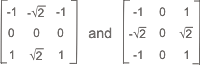
Frei Chen (M_FREI_CHEN), which can be represented with the following convolution kernels:
-
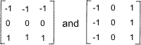
Prewitt (M_PREWITT), which can be represented with the following convolution kernels:
-
Sobel (M_SOBEL), which can be represented with the following convolution kernels:

Once you have allocated an Edge Finder context with the right context type (using MedgeAlloc()), you can customize the image processing algorithm using MedgeControl(). For example, to fit the requirements of your application, you can select the appropriate:
You can also choose to fill in the edge gaps, which is the process of linking broken edges together based on a set of criteria (M_FILL_GAP_DISTANCE and M_FILL_GAP_ANGLE).
Generally, the default control settings described in this section are sufficient for the majority of images. You should therefore adjust these settings only when dealing with very noisy images, extremely low or multi-contrast images, or images with very thin, refined features. In all cases, it is recommended that you try the default settings first and, if necessary, experiment with different settings to achieve the required edge map and accuracy.
For more advanced information on extracting edges, see the Advanced edge extraction section later in this chapter.
Note that the edge extraction process involves a denoising operation to even out rough edges and remove noise. The filter type, filter mode, kernel depth, noise reduction factor, and threshold mode all work in concert to control this operation, and ultimately determine which edges to extract. Changing any one of these factors will, to varying degrees, alter the edges that are extracted.
Filter type
The edge extraction filter is used to compute the source image's spatial derivatives, which in turn are used to calculate the edge's magnitude (Gradient or Hessian) and angle. It also establishes the contribution of each neighboring pixel to the edge calculation. You can set the type of filter used when performing the edge extraction using MedgeControl() with M_FILTER_TYPE. You can choose either an Infinite Impulse Response (IIR) edge extraction filter, or a Finite Impulse Response (FIR) edge extraction filter. The default filter type is the IIR filter, M_SHEN.
IIR filters allow you to extract both crests and contours, while FIR filters only allow you to extract contours. IIR filters take many more settings into account than FIR filters do. For example, IIR filters also allow you to take advantage of Edge Finder's smoothing capabilities, while FIR filters ignore your smoothness setting.
See "J.-P. Cocquerez and S. Philippe. Analyse d'images: filtrage et segmentation . Paris, France: Collection: Enseignement de la physique, 1995. " for more information on IIR and FIR filters.
Infinite Impulse Response (IIR) filters
MIL provides you with the following IIR filters to extract edges, which you can set using MedgeControl() with M_FILTER_TYPE:
These filters generate the weight values for neighboring pixels. In both cases, K corresponds to a normalization coefficient and a depends on the M_FILTER_SMOOTHNESS setting in MedgeControl(). Note that the general forms of these filters are not used directly; their first and second derivatives are used for contour and crest extraction, respectively.
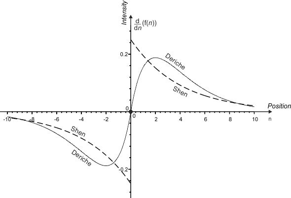
The default filter, Shen-Castan, typically performs an effective edge extraction; it achieves a very good localization of edges, which makes it ideal for the majority of images.
However, Shen-Castan can sometimes be unexpectedly sensitive to noise, or can yield inappropriate results if you are extracting unusually thick crests. If this is the case, you should try Deriche, which is better suited to handle these situations, since it places more emphasis on an edge's neighbors than Shen-Castan. The following image illustrates how the first derivative distribution of values can affect results for both Shen-Castan and Deriche:
Finite Impulse Response (FIR) filters
The M_FILTER_TYPE setting in MedgeControl() provides you with the following FIR filters to extract edges:
Note that, as mentioned, FIR filters only allow you to extract contours.
Smoothing for IIR filters
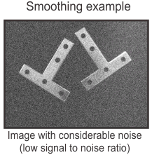
The M_FILTER_SMOOTHNESS setting in MedgeControl() allows you to control the degree of smoothness applied in the edge extraction. The smoothing operation evens out rough edges and reduces noise; in effect, the smoothness factor affects which edges are extracted.
The range of this control varies from 0 (no smooth) to 100 (a very strong smooth). The default setting is 50.0. Note that M_FILTER_SMOOTHNESS is only relevant if MedgeControl() with M_FILTER_TYPE is set to M_DERICHE or M_SHEN.
For recursive IIR filters, increasing the smoothness control value does not affect the processing time. A very high smoothing level can result in a loss of important detail and a decrease in precision. Note that, the range of smoothing is not linear; that is, the higher the smoothing factor, the greater the difference between settings. For example, changing the smoothing from 30.0 to 50.0 is less significant than changing the smoothing from 50.0 to 70.0.
The following animation demonstrates this non-linear change in smoothing:
Thresholding
Edge Finder determines which edges are extracted from the source image based on a thresholding of the magnitude of each edgel. More specifically, a hysteresis thresholding is used to perform the edge extraction. With this type of thresholding, the extracted edge chains are built such that the magnitude values of all connected edgels are stronger than the lower bound threshold value (M_THRESHOLD_LOW) and at least one edgel in each edge chain has a magnitude that is stronger than the upper bound threshold value (M_THRESHOLD_HIGH). For more information on edgel magnitude, see the Magnitude type subsection of this section.
Thresholding can also be applied during post-calculation. In this case, threshold settings are applied to the Edge Finder result buffer, rather than the source image. Except for filtering operations, the edge extraction process is completely recalculated. As a result, all internal processing buffers (M_SAVE_...) must have been initially saved, using MedgeControl(). For more information on post-calculation, see the Post-calculation subsection of the Calculating and retrieving results section later in this chapter.
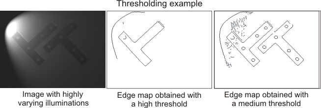
Edge Finder provides several predefined threshold modes that automatically select appropriate values for the lower and the upper bound thresholds, based on an internal image evaluation and noise estimation. To automatically determine the threshold settings with which to extract edges, call MedgeControl() with M_THRESHOLD_MODE set to one of the following: M_VERY_HIGH, M_HIGH, M_MEDIUM, M_LOW, or M_DISABLE. Note that lower threshold modes result in a more sensitive edgel detection.
The default setting (M_HIGH) is typically sufficient since it offers a robust detection of pertinent edgels, even from images presenting some contrast variations, noise, and non-uniform illumination. However, for multi-contrast images, or for images with a lot of noise or non-uniform illumination, some edges can be missed. In these cases, the setting M_MEDIUM should be used. If all relevant edges are still not being extracted, then use M_LOW, which will get all edges over a minimum noise-based estimated threshold. Finally, to extract all edgels in the image, use M_DISABLE, which will set the lower and upper bound threshold values to 0. Note that M_LOW and M_DISABLE should be used carefully since a large number of unnecessary edgels might be extracted. For images that have strong contrast, little noise, and consistent illumination, the M_VERY_HIGH setting can be used, since it will extract only the strongest edges. Note that M_VERY_HIGH should also be used carefully since pertinent edgels might not be extracted.
In the majority of cases, Edge Finder's predefined threshold modes should provide you with sufficient thresholding control. However, for advanced applications, you might want to explicitly set the threshold bounds. To do so, set M_THRESHOLD_MODE to M_USER_DEFINED, and use the M_THRESHOLD_LOW and M_THRESHOLD_HIGH control types to specify the lower and upper threshold bounds, respectively. The default settings are 0.
If M_THRESHOLD_MODE is not set to M_USER_DEFINED, your M_THRESHOLD_LOW and M_THRESHOLD_HIGH values have no effect.
Note that the threshold bounds must be provided as positive values. However, for line crests, Edge Finder will consider these values to be negative and/or positive, depending on whether the edges were extracted as darker (negative edgel values), lighter (positive edgel values), or both darker and lighter (negative and positive edgel values) than the image's background. For more information on extracting line crests, see the Object contours versus line crests subsection of the Extracting the edges section earlier in this chapter.
Advanced users might want to customize the behavior of the hysteresis thresholding; to do so, see the Advanced thresholding subsection of the Advanced edge extraction section later in this chapter.
Note that when interfacing with the MIL Geometric Model Finder module, you should use MedgeControl() with M_DETAIL_LEVEL to set the threshold mode. Note that an M_DETAIL_LEVEL setting overrides an M_THRESHOLD_MODE setting. For more information, see the Interfacing with Geometric Model Finder section later in this chapter.
See "P. L. Rosin Edges: Saliency measures and automatic thresholding . Ispara, Italy: Institute for Remote Sensing Applications, 1995. " for more information on automatic robust thresholding techniques for edge extraction.
Edgel accuracy
Edgels have a position and an angle. The M_ACCURACY and the M_ANGLE_ACCURACY settings in MedgeControl() determine the accuracy used to estimate edgel positions and angles.
M_ACCURACY determines edgel positional accuracy, and can be set to one of the following: M_HIGH, M_VERY_HIGH, or M_DISABLE. The default setting is M_HIGH. When you set the accuracy to high, edgel positions are calculated with subpixel accuracy, which is typically sufficient. When you set the accuracy to very high, a mathematical model is used to compensate for the deformation introduced by the square shape of each pixel, resulting in very precise subpixel edgel accuracy. If you want to disable subpixel accuracy and calculate edgels with pixel precision, set M_ACCURACY to M_DISABLE.
M_ANGLE_ACCURACY determines the precision with which to estimate edgel angles. By default, MIL uses a high degree of accuracy (M_HIGH), which establishes angles in increments of 360/256 degrees. To speed up the calculation, you can specify a lower degree of accuracy (M_LOW), which establishes angles in increments of 45 degrees.
By setting M_ACCURACY to M_HIGH and M_ANGLE_ACCURACY to M_LOW, Edge Finder will compute edgel positions with subpixel accuracy and edgel angles to the closest 45 degree increment. This results in a good estimate of the orientation of the maximum gradient with only a slight reduction in computation time.
Edgel accuracy varies with the image's dynamic range, sharpness, noise, and, to a lesser degree, with the orientation of the edge in the image. The best accuracy is achieved in well-contrasted, noise-free images. Theoretically, Edge Finder can provide a subpixel edgel location accuracy of up to 1/128th of a pixel. However, in real situations, it is reasonable to expect an accuracy from 1/10th of a pixel to 1/40th of a pixel, depending on physical limitations due to the transition's dynamic range and the image's noise.
You can notice the accuracy of the edgels if you draw the edges of a zoomed region of the source image. To do so, call MgraControl() with appropriate M_DRAW_OFFSET_X, M_DRAW_OFFSET_Y, M_DRAW_ZOOM_X, and M_DRAW_ZOOM_Y values, then call MedgeDraw() with M_DRAW_EDGE.

See "F. Devernay A Fast and Efficient Subpixelic Edge Detector . Mulhouse, France: INRIA. in Quatriemes Journees ORASIS (CNRS), 1993. " for more information on extracting the subpixel locations of edgels.
Magnitude type
You can specify the type of magnitude used to determine edgel positions using MedgeControl() with M_MAGNITUDE_TYPE. The magnitude type can be set to either M_NORM, where the gradient magnitude is used, or M_SQR_NORM, where the square of the gradient magnitude is used. The default setting is M_SQR_NORM.
Since M_SQR_NORM uses the square of the gradient magnitude, it is faster, though less precise than M_NORM. Typically, M_SQR_NORM is used since it preserves a very good edgel location accuracy. Note that changing M_MAGNITUDE_TYPE can slightly modify the resulting edge map.
Filling the edge gaps
Edge Finder allows you to fill gaps between edges; that is, it allows you to automatically link the extremities of non-closed edges together, depending on their relative positions and orientations. Unexpected broken edges can occur when dealing with noisy images, and connecting them can significantly improve the quality of your results. To help you choose which edges can be linked, Edge Finder provides a series of constraints, described below. Note that edges will only be linked if they adhere to each constraint.
Filling edge gaps can also be done in post-calculation; however, there are some restrictions that must be taken into account. For more information, see the Post-calculation subsection of the Calculating and retrieving results section later in this chapter.
Candidate constraint
You can choose whether to join an edge extremity with the other extremity of the same edge, or with an extremity of any edge. To connect an edge's extremity with the extremity of any edge, use MedgeControl() with M_FILL_GAP_CANDIDATE set to M_ANY. This is the default value.
To connect the edge extremities of the same edge, use MedgeControl() with M_FILL_GAP_CANDIDATE set to M_SAME. This is the same as closing an open edge. The following animation illustrates candidate constraints.

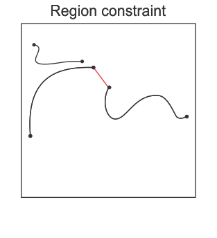
Region constraint
The M_FILL_GAP_DISTANCE and M_FILL_GAP_ANGLE settings in MedgeControl() define the region where two edge extremities can be linked. That is, when searching for edge extremity candidates to fill edge gaps, M_FILL_GAP_DISTANCE sets the maximum distance radius, while M_FILL_GAP_ANGLE sets the aperture angle; the origin of the aperture angle is the tangent line to the line segment at the point of interest. Note that two edge extremities can only be linked if both meet the M_FILL_GAP_DISTANCE and M_FILL_GAP_ANGLE criteria, and if both are included in the search region of the other. The following animation illustrates region constraints.
The gap distance (M_FILL_GAP_DISTANCE) must be specified in pixel units. The gap distance should be set carefully and large values should generally be avoided, otherwise the wrong edges can be connected. Typically, distance values should not exceed 5 pixels; however, if necessary, you can also specify no distance constraint (M_INFINITE). The default M_FILL_GAP_DISTANCE value is 0 (no edge linking) and the default M_FILL_GAP_ANGLE value is 360 degrees (all angles).
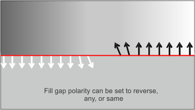
Polarity constraint
When searching for edge extremity candidates, you can also use the M_FILL_GAP_POLARITY control type to specify that only edges with a certain polarity can be linked. The edge's polarity indicates whether edges were established as a transition from light to dark, or vice versa. Two adjacent edgels will have "same polarity" if their angles are within a range of 180 degrees, and "reverse polarity" if their angles are outside the range of 180 degrees. By default (M_ANY), all edges that meet the distance and angle constraints are considered candidates, regardless of the edge's polarity. If M_FILL_GAP_POLARITY is set to M_SAME, only edges with the same polarity are considered potential candidates. If M_FILL_GAP_POLARITY is set to M_REVERSE, only edges with reverse polarity are considered potential candidates.
Note that the M_SAME and M_REVERSE polarity settings are not available for M_CREST Edge Finder contexts. The following animation illustrates polarity constraints.

Continuity constraint
It is possible that multiple edges meet the distance (M_FILL_GAP_DISTANCE), angle (M_FILL_GAP_ANGLE), and polarity (M_FILL_GAP_POLARITY) settings. When this occurs, you must decide which edges should be linked. To help choose, Edge Finder provides a continuity constraint.
The continuity constraint allows you to decide whether the candidate chosen to fill the edge gap is selected according to its proximity or its maximum continuity. To set the continuity constraint, use MedgeControl() with M_FILL_GAP_CONTINUITY. The range of this control varies from 0 to 100. When set to 0, the closest edge extremity is chosen to link edges together. When set to 100, the edge that gives the most continuous result (minimum curvature) is chosen. The default value is 50. In the following example, a candidate must be chosen to fill the gap with edge 1. If the continuity constraint is set to 100, edge 2 will be selected instead of edge 3; even though edge 3 is closer, edge 2 is more continuous. The following animation illustrates continuity constraints.