MmetAddTolerance
| MIL_ID ContextId, | //in |
| MIL_INT64 ToleranceType, | //in |
| MIL_INT ToleranceLabel, | //in |
| MIL_DOUBLE ValueMin, | //in |
| MIL_DOUBLE ValueMax, | //in |
| const MIL_INT *FeatureLabelArrayPtr, | //in |
| const MIL_INT *SubFeatureIndexArrayPtr, | //in |
| MIL_INT SizeOfArray, | //in |
| MIL_INT64 ControlFlag | //in |
This function adds a geometric tolerance to the metrology template of the specified metrology context. This function can also modify an existing tolerance of a metrology template. To delete geometric tolerances, use MmetControl() with M_DELETE.
To add several geometric tolerances, you must call this function for each tolerance to add.
A geometric tolerance defines the acceptable deviation from the definition of a feature, or the acceptable relationship between multiple features. For example, you can add a geometric tolerance to the metrology template to specify that one feature must be a certain length, or that two features must be perpendicular. To add a feature, use MmetAddFeature().
When adding a geometric tolerance that requires a point, you can use a specific point subfeature of a measured multiple point feature by specifying its index with the SubFeatureIndexArrayPtr parameter. Note that you cannot do this for other features, including the measured multiple edgel feature, as it is always used as a group.
When adding a geometric tolerance, you must also set its minimum and maximum limit values with the ValueMin and ValueMax parameters. When defining the tolerance of one feature, these limits represent the acceptable deviation from the definition of the feature. For example, a segment's length tolerance can be between 90 and 100 pixels. For multiple features, these limits represent the valid range of acceptable values between the features. For example, the perpendicular tolerance between two segments can be +/- 0.05° (that is, 89.95° to 90.05°). You can also set warning values to alert you when the tolerance is close to its minimum and maximum limits, using MmetControl() with M_VALUE_WARNING_MIN and M_VALUE_WARNING_MAX.
When you call MmetCalculate(), the tolerance is calculated (for example, 95 pixels) and a status is assigned (for example, M_PASS). To retrieve the tolerance value or the status, use MmetGetResult() with M_TOLERANCE_VALUE or M_STATUS, respectively.
You can modify a geometric tolerance (using M_MODIFY) so that it is based on a new set of features or subfeatures. As well, using M_MODIFY, you can modify the upper and lower bounds of a tolerance.
If a calibration context is associated with the target image, set values in real-world units (for example, tolerance values and warning values, and positional values). Otherwise use pixel units. For more information, see the Camera calibration - overview section of Chapter 25: Calibrating your camera setup.
Specifies the identifier of the metrology context. The metrology context must have been previously allocated on the required system using MmetAlloc().
Specifies the type of geometric tolerance to add. The symbol of every tolerance type is in its description. You can draw this symbol using MmetDraw() with M_DRAW_TOLERANCE.
 For adding geometric
tolerances
For adding geometric
tolerances |
|||||||||||||||||||||||||||||||||||||||
  Value Value |
Description
|
||||||||||||||||||||||||||||||||||||||
| M_ANGULARITY |
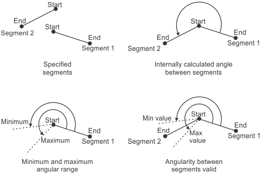
Adds an angularity tolerance. Its symbol
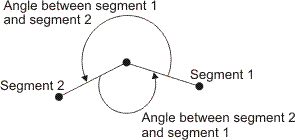
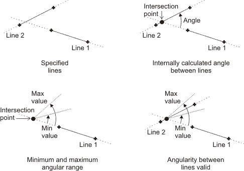
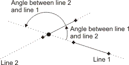
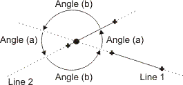
is An angularity tolerance validates that the angle between two features falls within the specified angular range (for example, that two lines intersect at an angle between 25° and 35°). An angularity tolerance can be applied between the following features.
Note that an angularity tolerance between a segment and a line produces too many ambiguities and therefore cannot be calculated. (summarize)Adds an angularity tolerance. (more details...) |
||||||||||||||||||||||||||||||||||||||
| M_CONCENTRICITY |
Adds a concentricity tolerance. Its
symbol is M_CONCENTRICITY validates the concentricity between a combination of two of the following features: arc or circle. This tolerance validates the distance between the centers of the features. Ideally, concentric features have the same center. The order of the features specified in the FeatureLabelArrayPtr parameter is inconsequential. 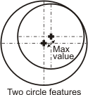
Adds a concentricity tolerance. (more details...) |
||||||||||||||||||||||||||||||||||||||
| M_DISTANCE_MAX |
Adds a maximum distance tolerance. Its
symbol is M_DISTANCE_MAX validates that a specified maximum distance is separating any two features (except lines). The order of the features specified in the FeatureLabelArrayPtr parameter is inconsequential. 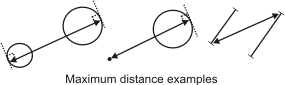
Adds a maximum distance tolerance. (more details...) |
||||||||||||||||||||||||||||||||||||||
| M_DISTANCE_MIN |
Adds a minimum distance tolerance. Its
symbol is M_DISTANCE_MIN validates that a specified minimum distance is separating any two features. The order of the features specified in the FeatureLabelArrayPtr parameter is inconsequential. 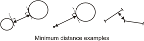
Adds a minimum distance tolerance. (more details...) |
||||||||||||||||||||||||||||||||||||||
|
M_LENGTH |
Adds a length tolerance. The symbol for an arc or circle length
tolerance is The symbol for a segment length
tolerance is M_LENGTH validates the length of one of the following features: segment, circle, or arc. The length of a circle is its circumference. 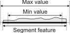
Adds a length tolerance. (more details...) |
||||||||||||||||||||||||||||||||||||||
| M_PARALLELISM |
Adds a parallelism tolerance. Its symbol
is A parallelism tolerance validates the degree to which two features are parallel. A parallelism tolerance can be applied between the following features:
For any combination of 2 linear features (segments and lines), M_PARALLELISM validates that the angle of the two features, relative to the global reference frame, is the same. The minimum and maximum tolerance parameters set the valid angular range, from the nominal angle (0°). The order of the features specified in the FeatureLabelArrayPtr parameter, as well as the start/end of the segments, is inconsequential. 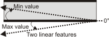
Note that, for parallelism tolerances between two linear features, angles are remapped to 0°; that is, the angle that is measured, and the angular range that you must provide, is the angle that is closest to 0°. 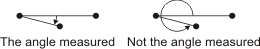
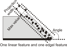
For a linear feature (segment or line) and an edgel feature, M_PARALLELISM validates the width of the projection of the edgel feature on a theoretical line that is perpendicular to the segment or line feature. The minimum and maximum tolerance values set the valid projection width. The smaller the width, the more the edgel feature is parallel to the given segment or line feature. Typically, the minimum width value is set to 0. The width of the projection is in pixel or world units. The second feature specified in the FeatureLabelArrayPtr parameter must be edgel. 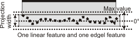
Adds a parallelism tolerance. (more details...) |
||||||||||||||||||||||||||||||||||||||
| M_PERPENDICULARITY |
Adds a perpendicularity tolerance. Its
symbol is A perpendicularity tolerance validates the degree to which two features are perpendicular. A perpendicularity tolerance can be applied between the following features:
For any combination of 2 linear features (segments and lines), M_PERPENDICULARITY validates that the angle between the two features is 90°. The minimum and maximum tolerance parameters set the valid angular range, from the nominal angle (90°). The order of the features specified in the FeatureLabelArrayPtr parameter, as well as the start/end of the segments, is inconsequential. 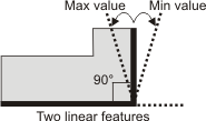
Note that, for perpendicularity tolerances between two linear features, angles are remapped to 90°; that is, the angle that is measured, and the angular range that you must provide, is the angle that is closest to 90°. 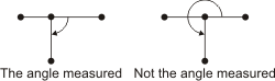
For a linear feature (segment or line) and an edgel feature, M_PERPENDICULARITY validates the width of the projection of the edgel feature on a theoretical line that is parallel to the segment or line feature. The minimum and maximum tolerance values set the valid projection width. The smaller the width, the more the edgel feature is perpendicular to the given segment or line feature. Typically, the minimum width value is set to 0. The width of the projection is in pixel or world units. The second feature specified in the FeatureLabelArrayPtr parameter must be edgel. 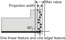
Adds a perpendicularity tolerance. (more details...) |
||||||||||||||||||||||||||||||||||||||
| M_POSITION_X |
Adds a positioning tolerance, along the
X-direction of the specified reference frame. Its symbol is
A positioning tolerance can be used to validate the geometric relationship between a reference frame and one of the following features: local frame, point, or circle. For a circle feature, only the position of its center is validated, not its contour. When using a positioning tolerance, the first element provided to the FeatureLabelArrayPtr parameter must be the label value of the reference frame, while the second element must be the label value of the feature to validate. 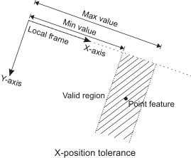
Adds a positioning tolerance, along the X-direction of the specified reference frame. (more details...) |
||||||||||||||||||||||||||||||||||||||
| M_POSITION_Y |
Adds a positioning tolerance, along the
Y-direction of the specified reference frame. Its symbol is
A positioning tolerance can be used to validate the geometric relationship between a reference frame and one of the following features: local frame, point, or circle. For a circle feature, only the position of its center is validated, not its contour. When using a positioning tolerance, the first element provided to the FeatureLabelArrayPtr parameter must be the label value of the reference frame, while the second element must be the label value of the feature to validate. 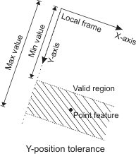
Adds a positioning tolerance, along the Y-direction of the specified reference frame. (more details...) |
||||||||||||||||||||||||||||||||||||||
|
M_RADIUS |
Adds a radius tolerance. Its symbol is
M_RADIUS validates the radius of the specified arc or circle feature. The radius is the linear length between the circle or arc's center and perimeter. 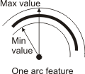
Adds a radius tolerance. (more details...) |
||||||||||||||||||||||||||||||||||||||
| M_ROUNDNESS |
Adds a roundness tolerance. Its symbol
is M_ROUNDNESS validates the roundness of one of the following features: arc or circle. For a circle, this is done by calculating the distance between the inner and outer circles formed by the given circle feature. Note that the inner and outer circles are concentric. The same concept applies to an arc feature, since an arc is a portion of a circle. 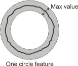
The same concept applies to an arc feature, since an arc is a portion of a circle. (summarize)Adds a roundness tolerance. (more details...) |
||||||||||||||||||||||||||||||||||||||
| M_STRAIGHTNESS |
Adds a straightness tolerance. Its
symbol is M_STRAIGHTNESS validates the straightness of one of the following features: segment or edgel. This is done by calculating the distance between the two parallel lines that are formed by the inner and outer boundaries of the feature. The angle of the two parallel lines is chosen such that the distance between them is the smallest. 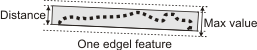
Adds a straightness tolerance. (more details...) |
||||||||||||||||||||||||||||||||||||||
To modify a geometric tolerance, the ToleranceType parameter can be set to the following value.
|
For modifying a geometric
tolerance |
|||||||||||||||||||||||||||||||||||||||
| Value |
Description
|
||||||||||||||||||||||||||||||||||||||
|
M_MODIFY |
Modifies both the set of features which the tolerance is based on, and the upper and lower bounds of the tolerance. (more details...) |
||||||||||||||||||||||||||||||||||||||
Specifies the label of the target tolerance.
|
For labeling the tolerance |
|||||||||||||||||||||||||||||||||||||||
| Value |
Description
|
||||||||||||||||||||||||||||||||||||||
|
M_DEFAULT |
Specifies that MIL automatically selects the tolerance's label value. (more details...) |
||||||||||||||||||||||||||||||||||||||
| Value > 0 |
Specifies the label value. (more details...) |
||||||||||||||||||||||||||||||||||||||
Specifies the array that holds the label values of the features whose relationship to validate. The features must have already been added to the metrology template of the metrology context. To add a feature, use MmetAddFeature().
Specifies the array that holds the index values of the multiple features' subfeatures whose relationship the added tolerance will validate. For non-multiple features (single features), specify 0 as the index. If the tolerance validates the relationship between only single features (there are no multiple features), set SubFeatureIndexArrayPtr to M_NULL.
Specifies the size of the arrays that hold the information that will be used to add the geometric tolerance (FeatureLabelArrayPtr and SubFeatureIndexArrayPtr).
| Header | Include mil.h. |
| Library | Use mil.lib; milmetrol.lib. |
| DLL | Requires mil.dll; milmetrol.dll. |