MmetControl
| MIL_ID MetId, | //in |
| MIL_INT LabelOrIndex, | //in |
| MIL_INT64 ControlType, | //in |
| MIL_DOUBLE ControlValue | //in |
This function sets the specified control for a metrology context, a derived metrology region object, features, tolerances, or a result buffer. These settings control the execution of MmetCalculate(), and affect how results are retrieved by MmetGetResult(). You can also use this function to specify whether features can be drawn with MmetDraw(). Most of the control type settings in MmetControl() can be inquired using MmetInquire().
If a calibration context is associated with the target image, set values in real-world units (for example, tolerance values, warning values, and positional values). Otherwise, use pixel units.
Specifies the identifier of the metrology context, the derived metrology region object, or the result buffer whose settings you want to control. The metrology context or the derived metrology region object must have been previously allocated on the required system using MmetAlloc(). The metrology result buffer must have been previously allocated on the required system using MmetAllocResult().
Specifies to control the metrology context, the derived metrology region object, features, tolerances, or the result buffer. Set this parameter to one of the following values.
 For specifying what to
control
For specifying what to
control |
|||||||||||||||||||||||||||||||||||||||
  Value Value |
Description
|
||||||||||||||||||||||||||||||||||||||
| M_DEFAULT |
Same as M_CONTEXT. |
||||||||||||||||||||||||||||||||||||||
|
|
Specifies the index value of an existing individual feature. (more details...) |
||||||||||||||||||||||||||||||||||||||
| Parameters | |||||||||||||||||||||||||||||||||||||||
|
This parameter specifies the index of the individual feature to which the control settings will be applied. You can set this parameter to the following: |
|||||||||||||||||||||||||||||||||||||||
|
|||||||||||||||||||||||||||||||||||||||
|
|
Specifies the label value of an existing individual feature. (more details...) |
||||||||||||||||||||||||||||||||||||||
| Parameters | |||||||||||||||||||||||||||||||||||||||
|
This parameter specifies the label of the individual feature to which the control settings will be applied. You can set this parameter to the following: |
|||||||||||||||||||||||||||||||||||||||
|
|||||||||||||||||||||||||||||||||||||||
|
|
Specifies the index value of an existing individual tolerance. (more details...) |
||||||||||||||||||||||||||||||||||||||
| Parameters | |||||||||||||||||||||||||||||||||||||||
|
This parameter specifies the index of the individual tolerance to which the control settings will be applied. You can set this parameter to the following: |
|||||||||||||||||||||||||||||||||||||||
|
|||||||||||||||||||||||||||||||||||||||
|
|
Specifies the label value of an existing individual tolerance. (more details...) |
||||||||||||||||||||||||||||||||||||||
| Parameters | |||||||||||||||||||||||||||||||||||||||
|
This parameter specifies the label of the individual tolerance to which the control settings will be applied. You can set this parameter to the following: |
|||||||||||||||||||||||||||||||||||||||
|
|||||||||||||||||||||||||||||||||||||||
| M_ALL_FEATURES |
Applies the specified control setting to all features. (more details...) |
||||||||||||||||||||||||||||||||||||||
| M_ALL_TOLERANCES |
Applies the specified control setting to all tolerances. |
||||||||||||||||||||||||||||||||||||||
| M_CONTEXT |
Controls a setting of the metrology context, which has been set using the MetId parameter. |
||||||||||||||||||||||||||||||||||||||
| M_DERIVED_GEOMETRY_REGION |
Controls a setting of the derived metrology region object, which has been set using the MetId parameter. |
||||||||||||||||||||||||||||||||||||||
| M_GENERAL |
Controls a setting of a metrology result buffer. (more details...) |
||||||||||||||||||||||||||||||||||||||
| M_GLOBAL_FRAME |
Applies the specified control setting to the global frame of the context. (more details...) |
||||||||||||||||||||||||||||||||||||||
| M_MEASURED_FEATURES |
Applies the specified control setting to all measured features. (more details...) |
||||||||||||||||||||||||||||||||||||||
Specifies the type of control to set.
See the Parameter associations section for possible values that can be specified.
Specifies the required value for the control.
See the Parameter associations section for possible values that can be specified.
The tables below list possible values for the ControlType and ControlValue parameters.
- For controlling general context settings
- For controlling global processing settings
- For controlling features
- For setting the geometry of the derived metrology region
- For setting the geometry data of the derived metrology region
- For controlling geometric tolerances
- For controlling features or geometric tolerances
- For controlling clone transformations
- For controlling results
- For deleting features and tolerances
The following ControlType and corresponding ControlValue parameter settings are used to control general metrology context settings. For controlling general context settings, the LabelOrIndex parameter must be set to M_CONTEXT and the MetId parameter must be set to a metrology context.
|
For controlling general context
settings |
|||||||||||||||||||||||||||||||||||||||
| ControlType |
Description
|
||||||||||||||||||||||||||||||||||||||
| ControlValue | |||||||||||||||||||||||||||||||||||||||
|
M_ASSOCIATED_CALIBRATION |
Associates the specified calibration context with the template reference of the metrology context. (more details...) |
||||||||||||||||||||||||||||||||||||||
| M_DEFAULT |
Same as M_NULL. |
||||||||||||||||||||||||||||||||||||||
| M_NULL |
Removes the association to the calibration. |
||||||||||||||||||||||||||||||||||||||
|
MIL Calibration context
identifier |
Specifies the identifier of the calibration context to associate with the template reference of the metrology context. |
||||||||||||||||||||||||||||||||||||||
|
M_TEMPLATE_REFERENCE_ID |
Associates a template reference to the context. INQ (more details...) |
||||||||||||||||||||||||||||||||||||||
| M_NULL |
Releases the template reference buffer. |
||||||||||||||||||||||||||||||||||||||
|
MIL image identifier |
Specifies the identifier of the buffer. |
||||||||||||||||||||||||||||||||||||||
|
M_TIMEOUT |
Sets the maximum measurement and validation time for MmetCalculate(). INQ (more details...) |
||||||||||||||||||||||||||||||||||||||
| M_DEFAULT |
Same as M_DISABLE. |
||||||||||||||||||||||||||||||||||||||
| M_DISABLE |
Specifies an infinite amount of measurement and validation time. |
||||||||||||||||||||||||||||||||||||||
| Value > 0.0 |
Specifies the maximum measurement and validation time, in msec. |
||||||||||||||||||||||||||||||||||||||
The following ControlType and corresponding ControlValue parameter settings are used to control processing settings for a measured feature. For controlling processing settings, the LabelOrIndex parameter can be set to M_MEASURED_FEATURES or an existing measured feature label or index using M_FEATURE_LABEL() or M_FEATURE_INDEX(). The MetId parameter must be set to a metrology context.
|
For controlling global processing
settings |
|||||||||||||||||||||||||||||||||||||||
| ControlType |
Description
|
||||||||||||||||||||||||||||||||||||||
| ControlValue | |||||||||||||||||||||||||||||||||||||||
|
M_CHAIN_ALL_NEIGHBORS |
Sets whether edge chains are built with as much edgel information as possible. INQ (more details...) |
||||||||||||||||||||||||||||||||||||||
| M_DEFAULT |
Same as M_ENABLE. |
||||||||||||||||||||||||||||||||||||||
| M_DISABLE |
Specifies that edge chains are built with the least amount of edgel information possible. 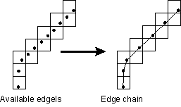
Specifies that edge chains are built with the least amount of edgel information possible. |
||||||||||||||||||||||||||||||||||||||
| M_ENABLE |
Specifies that edge chains are built with as much edgel information as possible. 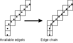
Enabling M_CHAIN_ALL_NEIGHBORS can result in greater accuracy, since edge chains can contain more information, though calculations can take slightly longer. (summarize)Specifies that edge chains are built with as much edgel information as possible. (more details...) |
||||||||||||||||||||||||||||||||||||||
|
M_EXTRACTION_SCALE |
Sets the scale of the image at which to do the edge extraction. INQ (more details...) |
||||||||||||||||||||||||||||||||||||||
| M_DEFAULT |
Specifies the default value; the default value is 1.0. |
||||||||||||||||||||||||||||||||||||||
| Value > 0.0 |
Specifies the extraction scale. |
||||||||||||||||||||||||||||||||||||||
|
M_FILTER_SMOOTHNESS |
Sets the degree of smoothness (strength of denoising) applied by the edge extraction filter during the neighborhood operation. INQ (more details...) |
||||||||||||||||||||||||||||||||||||||
| M_DEFAULT |
Specifies the default value; the default value is 50.0. |
||||||||||||||||||||||||||||||||||||||
|
0.0 <= Value <=
100.0 |
Specifies the smoothness value. (more details...) |
||||||||||||||||||||||||||||||||||||||
|
M_FILTER_TYPE |
Sets the type of filter used to extract edges. INQ (more details...) |
||||||||||||||||||||||||||||||||||||||
| M_DEFAULT |
Same as M_SHEN. |
||||||||||||||||||||||||||||||||||||||
| M_DERICHE |
Specifies a Canny-Deriche infinite support filter. |
||||||||||||||||||||||||||||||||||||||
| M_FREI_CHEN |
Specifies a Frei Chen filter. |
||||||||||||||||||||||||||||||||||||||
| M_PREWITT |
Specifies a Prewitt filter. |
||||||||||||||||||||||||||||||||||||||
| M_SHEN |
Specifies a Shen-Castan infinite support exponential filter. |
||||||||||||||||||||||||||||||||||||||
| M_SOBEL |
Specifies a Sobel filter. |
||||||||||||||||||||||||||||||||||||||
|
M_FLOAT_MODE |
Sets whether to perform all edge extraction operations using floating-point precision calculations. INQ (more details...) |
||||||||||||||||||||||||||||||||||||||
| M_DEFAULT |
Same as M_DISABLE. |
||||||||||||||||||||||||||||||||||||||
| M_DISABLE |
Specifies that all edge extractions are not forced to be performed using floating-point precision calculations. |
||||||||||||||||||||||||||||||||||||||
| M_ENABLE |
Specifies that all edge extractions are forced to be performed using floating-point precision calculations. |
||||||||||||||||||||||||||||||||||||||
|
M_MAGNITUDE_TYPE |
Sets how to calculate the magnitude of the edge at each edgel position. INQ (more details...) |
||||||||||||||||||||||||||||||||||||||
| M_DEFAULT |
Same as M_SQR_NORM. |
||||||||||||||||||||||||||||||||||||||
| M_NORM |
Specifies that the magnitude will be used. |
||||||||||||||||||||||||||||||||||||||
| M_SQR_NORM |
Specifies that the square of the magnitude will be used. |
||||||||||||||||||||||||||||||||||||||
|
M_REGION_ACCURACY_HIGH |
Sets the accuracy with which you define the metrology region associated with a feature when dealing with a calibrated image. INQ (more details...) |
||||||||||||||||||||||||||||||||||||||
| M_DEFAULT |
Same as M_ENABLE. |
||||||||||||||||||||||||||||||||||||||
| M_DISABLE |
Specifies that high accuracy is not used when defining a metrology region. (more details...) |
||||||||||||||||||||||||||||||||||||||
| M_ENABLE |
Specifies that high accuracy is used when defining a metrology region. |
||||||||||||||||||||||||||||||||||||||
|
M_THRESHOLD_MODE |
Sets the threshold of the edge extraction. INQ (more details...) |
||||||||||||||||||||||||||||||||||||||
| M_DEFAULT |
Same as M_HIGH. |
||||||||||||||||||||||||||||||||||||||
| M_DISABLE |
Specifies no threshold. (more details...) |
||||||||||||||||||||||||||||||||||||||
| M_HIGH |
Specifies a high threshold. (more details...) |
||||||||||||||||||||||||||||||||||||||
| M_LOW |
Specifies a low threshold. (more details...) |
||||||||||||||||||||||||||||||||||||||
| M_MEDIUM |
Specifies a medium threshold. (more details...) |
||||||||||||||||||||||||||||||||||||||
| M_USER_DEFINED |
Specifies that the threshold values will be user-defined. (more details...) |
||||||||||||||||||||||||||||||||||||||
| M_VERY_HIGH |
Specifies a very high threshold. (more details...) |
||||||||||||||||||||||||||||||||||||||
|
M_THRESHOLD_TYPE |
Sets the type of hysteresis threshold used when performing the edge extraction. INQ (more details...) |
||||||||||||||||||||||||||||||||||||||
| M_DEFAULT |
Same as M_HYSTERESIS. |
||||||||||||||||||||||||||||||||||||||
| M_FULL_HYSTERESIS |
Specifies that the lower bound threshold value is 0.0. |
||||||||||||||||||||||||||||||||||||||
| M_HYSTERESIS |
Specifies that both the lower bound threshold value and the upper bound threshold value will be used. |
||||||||||||||||||||||||||||||||||||||
| M_NO_HYSTERESIS |
Specifies that the lower bound threshold value is equal to the upper bound threshold value. |
||||||||||||||||||||||||||||||||||||||
|
M_THRESHOLD_VALUE_HIGH |
Sets the upper bound of the hysteresis threshold value. INQ (more details...) |
||||||||||||||||||||||||||||||||||||||
| M_DEFAULT |
Specifies the default value; the default value is 0.0. |
||||||||||||||||||||||||||||||||||||||
| Value |
Specifies the upper bound of the hysteresis threshold. |
||||||||||||||||||||||||||||||||||||||
|
M_THRESHOLD_VALUE_LOW |
Sets the lower bound of the hysteresis threshold value. INQ (more details...) |
||||||||||||||||||||||||||||||||||||||
| M_DEFAULT |
Specifies the default value; the default value is 0.0. |
||||||||||||||||||||||||||||||||||||||
| Value |
Specifies the lower bound of the hysteresis threshold. |
||||||||||||||||||||||||||||||||||||||
The following ControlType and corresponding ControlValue parameter settings are used to control how the features are calculated. For controlling features, the LabelOrIndex parameter can be set to the following: M_GLOBAL_FRAME or an existing feature label or index using M_FEATURE_LABEL() or M_FEATURE_INDEX(). The MetId parameter must be set to a metrology context.
|
For controlling features |
|||||||||||||||||||||||||||||||||||||||
| ControlType |
Description
|
||||||||||||||||||||||||||||||||||||||
| ControlValue | |||||||||||||||||||||||||||||||||||||||
|
M_ANGLE_END |
Sets the end angle of a constructed arc. INQ (more details...) |
||||||||||||||||||||||||||||||||||||||
| M_DEFAULT |
Specifies the default value; the default value is 360.0°. |
||||||||||||||||||||||||||||||||||||||
|
0.0 <= Value <= 360.0 |
Specifies the angle, in degrees. |
||||||||||||||||||||||||||||||||||||||
|
M_ANGLE_START |
Sets the start angle of a constructed arc. INQ (more details...) |
||||||||||||||||||||||||||||||||||||||
| M_DEFAULT |
Specifies the default value; the default value is 0.0°. |
||||||||||||||||||||||||||||||||||||||
|
0.0 <= Value <= 360.0 |
Specifies the angle, in degrees. |
||||||||||||||||||||||||||||||||||||||
|
M_EDGEL_ANGLE_RANGE |
Sets the angular range within which an edgel's gradient angle must fall for MIL to consider it an active edgel. Active edgels apply to physically measured features and constructed features based on physically measured edgels. By default, MIL measures the specified angular range, in the counter clockwise direction, relative to the metrology ROI's orientation. To change the relative angle from which to measure the angular range, use M_EDGEL_RELATIVE_ANGLE. In the following examples, the angular range is 60.0° and the relative angle is the same as the region's orientation. Note that for the ring-sector region, the orientation is radial. 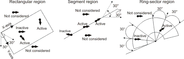
Note that constructed edgel features are not built from a region, but from a specified measured feature. Therefore in this case, the region's orientation refers to the orientation of the region from which its specified measured feature was built. INQ (summarize)Sets the angular range within which an edgel's gradient angle must fall for MIL to consider it an active edgel. INQ (more details...) |
||||||||||||||||||||||||||||||||||||||
| M_DEFAULT |
Specifies the default value; the default value is 180.0°. |
||||||||||||||||||||||||||||||||||||||
|
0.0 <= Value <=
360.0 |
Specifies the angular range, in degrees. |
||||||||||||||||||||||||||||||||||||||
|
M_EDGEL_RELATIVE_ANGLE |
Sets the relative angle from which to measure the gradient angle range (M_EDGEL_ANGLE_RANGE). INQ (more details...) |
||||||||||||||||||||||||||||||||||||||
| M_DEFAULT |
Same as M_SAME. |
||||||||||||||||||||||||||||||||||||||
| M_REVERSE |
Specifies that the gradient angle range is measured relative to the reverse angle (orientation) of the region of interest (+ 180°). |
||||||||||||||||||||||||||||||||||||||
| M_SAME |
Specifies that the gradient angle range is measured relative to the same angle (orientation) as the region of interest. |
||||||||||||||||||||||||||||||||||||||
|
M_SAME_OR_REVERSE |
Specifies that the gradient angle range is measured relative to either the same or the reverse angle (orientation) of the region of interest. |
||||||||||||||||||||||||||||||||||||||
|
M_EDGEL_SELECTION_RANK |
Sets the edgels to select relative to the orientation of the metrology region. The metrology region is scanned column by column, and the specified edgel encountered within a column is selected. Note that this control type takes effect after M_EDGEL_RELATIVE_ANGLE and M_EDGEL_ANGLE_RANGE are satisfied. M_EDGEL_SELECTION_RANK applies to M_RECTANGLE derived metrology regions. In the following example, there are multiple edges in the metrology region. The solid gray line illustrates the edgels selected when M_EDGEL_SELECTION_RANK is set to 1; the dotted gray line illustrates the edgels selected when M_EDGEL_SELECTION_RANK is set to 2. INQ 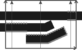
Sets the edgels to select relative to the orientation of the metrology region. INQ (more details...) |
||||||||||||||||||||||||||||||||||||||
| M_DEFAULT |
Same as M_DISABLE. |
||||||||||||||||||||||||||||||||||||||
| M_DISABLE |
Specifies that all edgels are selected. |
||||||||||||||||||||||||||||||||||||||
| M_LAST |
Selects the last edgel in each column, relative to the metrology region. |
||||||||||||||||||||||||||||||||||||||
| Value > 0 |
Specifies which edgels to select, based on their rank, relative to the metrology region. |
||||||||||||||||||||||||||||||||||||||
|
M_EDGEL_TYPE |
Sets the type of edgels to use when building constructed edgel features from a measured base feature using MmetAddFeature() with M_COPY_FEATURE_EDGELS. INQ (more details...) |
||||||||||||||||||||||||||||||||||||||
| M_DEFAULT |
Same as M_ACTIVE_EDGELS. |
||||||||||||||||||||||||||||||||||||||
| M_ACTIVE_EDGELS |
Specifies to use the active edgels of the measured feature's metrology region. (more details...) |
||||||||||||||||||||||||||||||||||||||
| M_ALL_EDGELS |
Specifies to use all the edgels of the measured feature's metrology region. |
||||||||||||||||||||||||||||||||||||||
| M_FITTED_EDGELS |
Specifies to use the fitted edgels of the measured feature's metrology region. (more details...) |
||||||||||||||||||||||||||||||||||||||
|
M_FIT_COVERAGE_MIN |
Sets the approximate portion of the feature that must be covered by fitted edgels. In the following example, about 50.0% of the segment feature covers the edgels. 
The actual coverage that results from this setting depends on the scale of the image at which the feature edges were extracted, as specified with M_EXTRACTION_SCALE; a scale of 1 provides the best estimation. M_FIT_COVERAGE_MIN is valid for all fit operations for physically measured or constructed features. For constructed features using a fit operation performed on multiple physically measured edgel features, the accuracy of the minimum fit coverage is based on the average of each feature's extraction scale. INQ (summarize)Sets the approximate portion of the feature that must be covered by fitted edgels. INQ (more details...) |
||||||||||||||||||||||||||||||||||||||
| M_DEFAULT |
Specifies the default value; the default value is 0.0%. |
||||||||||||||||||||||||||||||||||||||
|
0.0 <= Value <=
100.0 |
Specifies the minimum coverage, as a percentage. |
||||||||||||||||||||||||||||||||||||||
|
M_FIT_DISTANCE_MAX |
Sets the greatest possible gap between an active edgel and an iterative fit for the edgel to be considered during the next iteration. INQ (more details...) |
||||||||||||||||||||||||||||||||||||||
| M_DEFAULT |
Same as M_INFINITE. |
||||||||||||||||||||||||||||||||||||||
| M_INFINITE |
Specifies no maximum distance. |
||||||||||||||||||||||||||||||||||||||
| Value |
Specifies the maximum distance, in pixel units. |
||||||||||||||||||||||||||||||||||||||
|
M_FIT_ITERATIONS_MAX |
Sets the maximum number of fit iterations used to compute the feature. INQ (more details...) |
||||||||||||||||||||||||||||||||||||||
| M_DEFAULT |
Same as M_AUTO. |
||||||||||||||||||||||||||||||||||||||
| M_AUTO |
Specifies that the maximum number of fit iterations will be automatically determined. |
||||||||||||||||||||||||||||||||||||||
| Value >= 1 |
Specifies the maximum number of fit iterations. (more details...) |
||||||||||||||||||||||||||||||||||||||
|
M_FIT_VARIATION_MAX |
Sets the maximum allowable difference in the value of the feature's underlying coefficients, from one fit iteration to the next. INQ (more details...) |
||||||||||||||||||||||||||||||||||||||
| M_DEFAULT |
Same as M_AUTO. |
||||||||||||||||||||||||||||||||||||||
| M_AUTO |
Specifies that the maximum variation will be determined automatically. |
||||||||||||||||||||||||||||||||||||||
|
0.0 <= Value <=
100.0 |
Specifies the maximum variation, as a percentage. |
||||||||||||||||||||||||||||||||||||||
|
M_LINE_A |
Sets the coefficient A of the line equation for a parametrically constructed line. INQ (more details...) |
||||||||||||||||||||||||||||||||||||||
| M_DEFAULT |
Specifies the default value; the default value is 0.0. |
||||||||||||||||||||||||||||||||||||||
| Value |
Specifies the coefficient's value. |
||||||||||||||||||||||||||||||||||||||
|
M_LINE_B |
Sets the coefficient B of the line equation for a parametrically constructed line. INQ (more details...) |
||||||||||||||||||||||||||||||||||||||
| M_DEFAULT |
Specifies the default value; the default value is 1.0. |
||||||||||||||||||||||||||||||||||||||
| Value |
Specifies the coefficient's value. |
||||||||||||||||||||||||||||||||||||||
|
M_LINE_C |
Sets the coefficient C of the line equation for a parametrically constructed line. INQ (more details...) |
||||||||||||||||||||||||||||||||||||||
| M_DEFAULT |
Specifies the default value; the default value is 0.0. |
||||||||||||||||||||||||||||||||||||||
| Value |
Specifies the coefficient's value. |
||||||||||||||||||||||||||||||||||||||
|
M_NUMBER_MAX |
Sets the maximum number of subfeatures to calculate for a multiple feature. INQ (more details...) |
||||||||||||||||||||||||||||||||||||||
| M_DEFAULT |
Specifies the default value; the default value is 1. |
||||||||||||||||||||||||||||||||||||||
| Value |
Specifies the maximum number of subfeatures. (more details...) |
||||||||||||||||||||||||||||||||||||||
|
M_NUMBER_MIN |
Sets the minimum number of subfeatures to calculate for a multiple feature. INQ (more details...) |
||||||||||||||||||||||||||||||||||||||
| M_DEFAULT |
Specifies the default value; the default value is 0. |
||||||||||||||||||||||||||||||||||||||
| Value |
Specifies the minimum number of subfeatures. (more details...) |
||||||||||||||||||||||||||||||||||||||
|
M_OCCURRENCE |
Sets the point to use if there is more than one candidate when adding a constructed point feature built at the intersection of two base features (MmetAddFeature() with M_POINT and M_INTERSECTION or M_EXTENDED_INTERSECTION). INQ (more details...) |
||||||||||||||||||||||||||||||||||||||
| M_DEFAULT |
Specifies the default value; the default value is 0. |
||||||||||||||||||||||||||||||||||||||
| Index |
Specifies the index value. |
||||||||||||||||||||||||||||||||||||||
|
M_POSITION |
Sets the position, along the contour of the specified base feature, at which to construct the point feature (MmetAddFeature() with M_POINT and M_POSITION_ABSOLUTE or M_POSITION_RELATIVE). INQ (more details...) |
||||||||||||||||||||||||||||||||||||||
| M_DEFAULT |
Specifies the default value; the default value is 0. |
||||||||||||||||||||||||||||||||||||||
| Value |
Specifies the position value. (more details...) |
||||||||||||||||||||||||||||||||||||||
|
M_POSITION_END_X |
Sets the X-coordinate of the end point of a segment constructed using MmetAddFeature() with M_PARAMETRIC. INQ (more details...) |
||||||||||||||||||||||||||||||||||||||
| M_DEFAULT |
Specifies the default value; the default value is 1.0. |
||||||||||||||||||||||||||||||||||||||
| Value |
Specifies the X-coordinate, in pixel or world units. |
||||||||||||||||||||||||||||||||||||||
|
M_POSITION_END_Y |
Sets the Y-coordinate of the end point of a segment constructed using MmetAddFeature() with M_PARAMETRIC. INQ (more details...) |
||||||||||||||||||||||||||||||||||||||
| M_DEFAULT |
Specifies the default value; the default value is 0.0. |
||||||||||||||||||||||||||||||||||||||
| Value |
Specifies the Y-coordinate, in pixel or world units. |
||||||||||||||||||||||||||||||||||||||
|
M_POSITION_START_X |
Sets the X-coordinate of the start point of a segment constructed using MmetAddFeature() with M_PARAMETRIC. INQ (more details...) |
||||||||||||||||||||||||||||||||||||||
| M_DEFAULT |
Specifies the default value; the default value is -1.0. |
||||||||||||||||||||||||||||||||||||||
| Value |
Specifies the X-coordinate, in pixel or world units. |
||||||||||||||||||||||||||||||||||||||
|
M_POSITION_START_Y |
Sets the Y-coordinate of the start point of a segment constructed using MmetAddFeature() with M_PARAMETRIC. INQ (more details...) |
||||||||||||||||||||||||||||||||||||||
| M_DEFAULT |
Specifies the default value; the default value is 0.0. |
||||||||||||||||||||||||||||||||||||||
| Value |
Specifies the Y-coordinate, in pixel or world units. |
||||||||||||||||||||||||||||||||||||||
|
M_POSITION_X |
Sets the X-coordinate of the center of a constructed circle or arc, or sets the X-coordinate of a constructed local frame or point. INQ (more details...) |
||||||||||||||||||||||||||||||||||||||
| M_DEFAULT |
Specifies the default value; the default value is 0.0. |
||||||||||||||||||||||||||||||||||||||
| Value |
Specifies the X-coordinate, in pixel or world units. |
||||||||||||||||||||||||||||||||||||||
|
M_POSITION_Y |
Sets the Y-coordinate of the center of a constructed circle or arc, or sets the Y-coordinate of a constructed local frame or point. INQ (more details...) |
||||||||||||||||||||||||||||||||||||||
| M_DEFAULT |
Specifies the default value; the default value is 0.0. |
||||||||||||||||||||||||||||||||||||||
| Value |
Specifies the Y-coordinate, in pixel or world units. |
||||||||||||||||||||||||||||||||||||||
|
M_RADIUS |
Sets the radius of a constructed circle or arc. INQ (more details...) |
||||||||||||||||||||||||||||||||||||||
| M_DEFAULT |
Specifies the default value; the default value is 0.0. |
||||||||||||||||||||||||||||||||||||||
| Value |
Specifies the radius, in pixel or world units. |
||||||||||||||||||||||||||||||||||||||
|
M_REFERENCE_FRAME |
Sets the feature's reference frame. INQ (more details...) |
||||||||||||||||||||||||||||||||||||||
| M_DEFAULT |
Specifies that the reference frame is the global frame. |
||||||||||||||||||||||||||||||||||||||
| Label |
Specifies the label of the reference frame. |
||||||||||||||||||||||||||||||||||||||
|
M_SORT |
Sets the sorting order that MIL applies to the index of subpoints, when retrieving results of multiple point features. INQ (more details...) |
||||||||||||||||||||||||||||||||||||||
| M_DEFAULT |
Same as M_SORT_UP. |
||||||||||||||||||||||||||||||||||||||
| M_SORT_DOWN |
Specifies that results of multiple point features are sorted in descending order, according to the subpoint's index. |
||||||||||||||||||||||||||||||||||||||
| M_SORT_UP |
Specifies that results of multiple point features are sorted in ascending order, according to the subpoint's index. |
||||||||||||||||||||||||||||||||||||||
The following ControlType and corresponding ControlValue parameter settings are used to set the geometry of the derived metrology region. In this case, the LabelOrIndex parameter must be set to M_DERIVED_GEOMETRY_REGION and the MetId parameter must be set to a derived metrology region object. You must also call MmetSetRegion() with M_FROM_DERIVED_GEOMETRY_REGION and specify the label or index of the measured feature that will be established from the area delimited by the derived metrology region.
|
For setting the geometry of the derived
metrology region |
|||||||||||||||||||||||||||||||||||||||
| ControlType |
Description
|
||||||||||||||||||||||||||||||||||||||
| ControlValue | |||||||||||||||||||||||||||||||||||||||
|
M_REGION_GEOMETRY |
Sets the geometry of the derived metrology region. INQ (more details...) |
||||||||||||||||||||||||||||||||||||||
| M_DEFAULT |
Same as M_INFINITE. |
||||||||||||||||||||||||||||||||||||||
| M_ARC |
Specifies that the feature will be established with an arc metrology region. You can use M_ARC to establish point features. To define an arc metrology region, you must set its end angle (M_REGION_ANGLE_END), start angle (M_REGION_ANGLE_START), position (M_REGION_POSITION or M_REGION_POSITION_X and M_REGION_POSITION_Y), and radius (M_REGION_RADIUS). 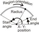
Specifies that the feature will be established with an arc metrology region. (more details...) |
||||||||||||||||||||||||||||||||||||||
| M_INFINITE |
Specifies that the feature will be established with an infinite metrology region. (more details...) |
||||||||||||||||||||||||||||||||||||||
| M_RECTANGLE |
Specifies that the feature will be established with a rectangle metrology region. You can use M_RECTANGLE to establish segment or edgel features. To define a rectangle metrology region, you must set its angle (M_REGION_ANGLE), height (M_REGION_HEIGHT), position (M_REGION_POSITION or M_REGION_POSITION_X and M_REGION_POSITION_Y), and width (M_REGION_WIDTH). 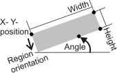
Specifies that the feature will be established with a rectangle metrology region. (more details...) |
||||||||||||||||||||||||||||||||||||||
| M_RING |
Specifies that the feature will be established with a ring metrology region. You can use M_RING to establish circle or edgel features. To define a ring metrology region, you must set its position (M_REGION_POSITION or M_REGION_POSITION_X and M_REGION_POSITION_Y), end radius (M_REGION_RADIUS_END), and start radius (M_REGION_RADIUS_START). 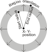
Specifies that the feature will be established with a ring metrology region. (more details...) |
||||||||||||||||||||||||||||||||||||||
| M_RING_SECTOR |
Specifies that the feature will be established with a ring-sector metrology region. You can use M_RING_SECTOR to establish radial segment, arc, or edgel features. To define a ring-sector metrology region, you must set its end angle (M_REGION_ANGLE_END), start angle (M_REGION_ANGLE_START), position (M_REGION_POSITION or M_REGION_POSITION_X and M_REGION_POSITION_Y), end radius (M_REGION_RADIUS_END) and start radius (M_REGION_RADIUS_START). 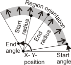
Specifies that the feature will be established with a ring-sector metrology region. (more details...) |
||||||||||||||||||||||||||||||||||||||
| M_SEGMENT |
Specifies that the feature will be established with a linear segment metrology region. You can use M_SEGMENT to establish point features. To define a linear segment metrology region, you must set its end point (M_REGION_END or M_REGION_END_X and M_REGION_END_Y), and start point (M_REGION_START or M_REGION_START_X and M_REGION_START_Y). 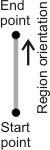
Specifies that the feature will be established with a linear segment metrology region. (more details...) |
||||||||||||||||||||||||||||||||||||||
The following ControlType and corresponding ControlValue parameter settings are used to set the geometry data required to define a derived metrology region. In this case, the LabelOrIndex parameter must be set to M_DERIVED_GEOMETRY_REGION and the MetId parameter must be set to a derived metrology region object.
The controls in the following table that you must set depend on the geometry specified with M_REGION_GEOMETRY.
|
For setting the geometry data of the
derived metrology region |
|||||||||||||||||||||||||||||||||||||||
| ControlType |
Description
|
||||||||||||||||||||||||||||||||||||||
| ControlValue | |||||||||||||||||||||||||||||||||||||||
|
M_REGION_ANGLE |
Sets the angle of the derived metrology region, relative to the reference frame. INQ (more details...) |
||||||||||||||||||||||||||||||||||||||
| M_DEFAULT |
Specifies the default value; the default value is 0.0°. |
||||||||||||||||||||||||||||||||||||||
| M_RADIAL |
Specifies that the infinite metrology region has a radial orientation, from 0.0° to 360.0°, based on the specified position (M_REGION_POSITION). M_RADIAL applies to M_INFINITE only. 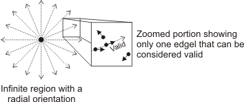
In such a region, edgels can only be considered part of the physically measured feature if their gradient angle conforms to the direction of a radii pointing out from the region's position. M_RADIAL is usually used to define a metrology region for a physically measured circular feature whose radius is unknown. Typically the position of this metrology region is placed at the feature's center, resulting in valid edgels only being possible if they encircle the position. (summarize)Specifies that the infinite metrology region has a radial orientation, from 0.0° to 360.0°, based on the specified position (M_REGION_POSITION). (more details...) |
||||||||||||||||||||||||||||||||||||||
|
0.0 <= Value <=
360.0 |
Specifies the angle, in degrees. (more details...) |
||||||||||||||||||||||||||||||||||||||
| Label |
Specifies the label of a point feature, which metrology uses to set the angle of the derived metrology region. In this case, you must set M_REGION_ANGLE_TYPE to M_FEATURE_LABEL_VALUE. When specifying the label of a point, MIL considers the angle to be between the X-axis along the metrology region's position (for example, M_REGION_POSITION), and a theoretical straight line that connects that position to the specified point feature. By default, the X-axis along the metrology region's position is aligned along the X-axis of the reference frame. The following example shows how a specified point establishes the angle of a rectangle metrology region. 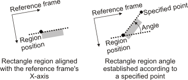
Specifies the label of a point feature, which metrology uses to set the angle of the derived metrology region. (more details...) |
||||||||||||||||||||||||||||||||||||||
|
M_REGION_ANGLE_END |
Sets the end angle of the derived metrology region, relative to the reference frame. INQ (more details...) |
||||||||||||||||||||||||||||||||||||||
| M_DEFAULT |
Specifies the default value; the default value is 360.0°. |
||||||||||||||||||||||||||||||||||||||
|
0.0 <= Value <=
360.0 |
Specifies the angle, in degrees. (more details...) |
||||||||||||||||||||||||||||||||||||||
| Label |
Specifies the label of a point feature, which metrology uses to set the end angle of the metrology region. In this case, you must set M_REGION_ANGLE_END_TYPE to M_FEATURE_LABEL_VALUE. When specifying the label of a point, MIL considers the end angle to be between the X-axis along the metrology region's position (for example, M_REGION_POSITION), and a theoretical straight line that connects that position to the specified point feature. By default, the X-axis along the metrology region's position is aligned along the X-axis of the reference frame. The following example shows how a specified point establishes the end angle of an arc metrology region. The example also shows how a specified point establishes the start angle of an arc metrology region (M_REGION_ANGLE_START). 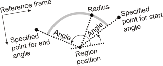
Specifies the label of a point feature, which metrology uses to set the end angle of the metrology region. (more details...) |
||||||||||||||||||||||||||||||||||||||
|
M_REGION_ANGLE_END_TYPE |
Sets whether you are using a feature or an explicit value to specify the end angle of the derived metrology region (M_REGION_ANGLE_END). INQ (more details...) |
||||||||||||||||||||||||||||||||||||||
| M_DEFAULT |
Same as M_PARAMETRIC. |
||||||||||||||||||||||||||||||||||||||
|
M_FEATURE_LABEL_VALUE |
Specifies to use a feature. |
||||||||||||||||||||||||||||||||||||||
| M_PARAMETRIC |
Specifies to use an explicit value. |
||||||||||||||||||||||||||||||||||||||
|
M_REGION_ANGLE_START |
Sets the start angle of the derived metrology region, relative to the reference frame. INQ (more details...) |
||||||||||||||||||||||||||||||||||||||
| M_DEFAULT |
Specifies the default value; the default value is 0.0°. |
||||||||||||||||||||||||||||||||||||||
|
0.0 <= Value <=
360.0 |
Specifies the angle, in degrees. (more details...) |
||||||||||||||||||||||||||||||||||||||
| Label |
Specifies the label of a point feature, which metrology uses to set the start angle of the metrology region. In this case, you must set M_REGION_ANGLE_START_TYPE to M_FEATURE_LABEL_VALUE. When specifying the label of a point, MIL considers the start angle to be between the X-axis along the metrology region's position (for example, M_REGION_POSITION), and a theoretical straight line that connects that position to the specified point feature. By default, the X-axis along the metrology region's position is aligned along the X-axis of the reference frame. The following example shows how a specified point establishes the start angle of an arc metrology region. The example also shows how a specified point establishes the end angle of an arc metrology region (M_REGION_ANGLE_END).
Specifies the label of a point feature, which metrology uses to set the start angle of the metrology region. (more details...) |
||||||||||||||||||||||||||||||||||||||
|
M_REGION_ANGLE_START_TYPE |
Sets whether you are using a feature or an explicit value to specify the start angle of the derived metrology region (M_REGION_ANGLE_START). INQ (more details...) |
||||||||||||||||||||||||||||||||||||||
| M_DEFAULT |
Same as M_PARAMETRIC. |
||||||||||||||||||||||||||||||||||||||
|
M_FEATURE_LABEL_VALUE |
Specifies to use a feature. |
||||||||||||||||||||||||||||||||||||||
| M_PARAMETRIC |
Specifies to use an explicit value. |
||||||||||||||||||||||||||||||||||||||
|
M_REGION_ANGLE_TYPE |
Sets whether you are using a feature or an explicit value to specify the angle of the derived metrology region (M_REGION_ANGLE). INQ (more details...) |
||||||||||||||||||||||||||||||||||||||
| M_DEFAULT |
Same as M_PARAMETRIC. |
||||||||||||||||||||||||||||||||||||||
|
M_FEATURE_LABEL_VALUE |
Specifies to use a feature. |
||||||||||||||||||||||||||||||||||||||
| M_PARAMETRIC |
Specifies to use an explicit value. |
||||||||||||||||||||||||||||||||||||||
|
M_REGION_END |
Sets the end point of the derived metrology region. INQ (more details...) |
||||||||||||||||||||||||||||||||||||||
| Label |
Specifies the label of a point feature, which metrology uses to set the end point of the metrology region. |
||||||||||||||||||||||||||||||||||||||
|
M_REGION_END_TYPE |
Sets whether you are using a feature or an explicit value to specify the end point of the derived metrology region (M_REGION_END, or M_REGION_END_X and M_REGION_END_Y). INQ (more details...) |
||||||||||||||||||||||||||||||||||||||
| M_DEFAULT |
Same as M_PARAMETRIC. |
||||||||||||||||||||||||||||||||||||||
|
M_FEATURE_LABEL_VALUE |
Specifies to use a feature. |
||||||||||||||||||||||||||||||||||||||
| M_PARAMETRIC |
Specifies to use an explicit value. |
||||||||||||||||||||||||||||||||||||||
|
M_REGION_END_X |
Sets the X-coordinate of the end point of the derived metrology region, relative to the reference frame. INQ (more details...) |
||||||||||||||||||||||||||||||||||||||
| M_DEFAULT |
Specifies the default value; the default value is 0.0. |
||||||||||||||||||||||||||||||||||||||
| Value |
Specifies the end point's X-coordinate, in pixel or world units. |
||||||||||||||||||||||||||||||||||||||
|
M_REGION_END_Y |
Sets the Y-coordinate of the end point of the derived metrology region, relative to the reference frame. INQ (more details...) |
||||||||||||||||||||||||||||||||||||||
| M_DEFAULT |
Specifies the default value; the default value is 0.0. |
||||||||||||||||||||||||||||||||||||||
| Value |
Specifies the end point's Y-coordinate, in pixel or world units. |
||||||||||||||||||||||||||||||||||||||
|
M_REGION_HEIGHT |
Sets the height of the derived metrology region. INQ (more details...) |
||||||||||||||||||||||||||||||||||||||
| M_DEFAULT |
Specifies the default value; the default value is 0.0 pixels. |
||||||||||||||||||||||||||||||||||||||
| Label |
Specifies the label of a point feature, which metrology uses to set the rectangle's height. In this case, you must set M_REGION_HEIGHT_TYPE to M_FEATURE_LABEL_VALUE. When specifying the label of a point, MIL considers the height to be at the perpendicular intersection point between the Y-axis along the metrology region's position (for example, M_REGION_POSITION), and the X-axis along the specified point feature. By default, the X- and Y-axes along the metrology region's position and along the specified point are aligned with the reference frame. The example also shows how a specified point establishes the width of a rectangle metrology region (M_REGION_WIDTH). 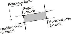
Specifies the label of a point feature, which metrology uses to set the rectangle's height. (more details...) |
||||||||||||||||||||||||||||||||||||||
| Value |
Specifies the rectangle's height, in pixel or world units. (more details...) |
||||||||||||||||||||||||||||||||||||||
|
M_REGION_HEIGHT_TYPE |
Sets whether you are using a feature or an explicit value to specify the height of the derived metrology region (M_REGION_HEIGHT). INQ (more details...) |
||||||||||||||||||||||||||||||||||||||
| M_DEFAULT |
Same as M_PARAMETRIC. |
||||||||||||||||||||||||||||||||||||||
|
M_FEATURE_LABEL_VALUE |
Specifies to use a feature. |
||||||||||||||||||||||||||||||||||||||
| M_PARAMETRIC |
Specifies to use an explicit value. |
||||||||||||||||||||||||||||||||||||||
|
M_REGION_POSITION |
Sets the position of the derived metrology region. INQ (more details...) |
||||||||||||||||||||||||||||||||||||||
| Label |
Specifies the label of a point feature, which metrology uses to set the position of the metrology region. |
||||||||||||||||||||||||||||||||||||||
|
M_REGION_POSITION_TYPE |
Sets whether you are using a feature or an explicit value to specify the position of the derived metrology region (M_REGION_POSITION, or M_REGION_POSITION_X and M_REGION_POSITION_Y). INQ (more details...) |
||||||||||||||||||||||||||||||||||||||
| M_DEFAULT |
Same as M_PARAMETRIC. |
||||||||||||||||||||||||||||||||||||||
|
M_FEATURE_LABEL_VALUE |
Specifies to use a feature. |
||||||||||||||||||||||||||||||||||||||
| M_PARAMETRIC |
Specifies to use an explicit value. |
||||||||||||||||||||||||||||||||||||||
|
M_REGION_POSITION_X |
Sets the X-coordinate of the position of the derived metrology region, relative to the reference frame. INQ (more details...) |
||||||||||||||||||||||||||||||||||||||
| M_DEFAULT |
Specifies the default value; the default value is 0.0. |
||||||||||||||||||||||||||||||||||||||
| Value |
Specifies the position's X-coordinate, in pixel or world units. |
||||||||||||||||||||||||||||||||||||||
|
M_REGION_POSITION_Y |
Sets the Y-coordinate of the position of the derived metrology region, relative to the reference frame. INQ (more details...) |
||||||||||||||||||||||||||||||||||||||
| M_DEFAULT |
Specifies the default value; the default value is 0.0. |
||||||||||||||||||||||||||||||||||||||
| Value |
Specifies the position's Y-coordinate, in pixel or world units. |
||||||||||||||||||||||||||||||||||||||
|
M_REGION_RADIUS |
Sets the radius of the derived metrology region. INQ (more details...) |
||||||||||||||||||||||||||||||||||||||
| M_DEFAULT |
Specifies the default value; the default value is 0.0 pixels. |
||||||||||||||||||||||||||||||||||||||
| Label |
Specifies the label of a point feature, which metrology uses to set the arc's radius. (more details...) |
||||||||||||||||||||||||||||||||||||||
| Value |
Specifies the radius, in pixel or world units. (more details...) |
||||||||||||||||||||||||||||||||||||||
|
M_REGION_RADIUS_END |
Sets the end radius of the derived metrology region. INQ (more details...) |
||||||||||||||||||||||||||||||||||||||
| M_DEFAULT |
Specifies the default value; the default value is 0.0 pixels. |
||||||||||||||||||||||||||||||||||||||
| Label |
Specifies the label of a point feature, which metrology uses to set the end radius. (more details...) |
||||||||||||||||||||||||||||||||||||||
| Value |
Specifies the end radius, in pixel or world units. (more details...) |
||||||||||||||||||||||||||||||||||||||
|
M_REGION_RADIUS_END_TYPE |
Sets whether you are using a feature or an explicit value to specify the end radius of the derived metrology region (M_REGION_RADIUS_END). INQ (more details...) |
||||||||||||||||||||||||||||||||||||||
| M_DEFAULT |
Same as M_PARAMETRIC. |
||||||||||||||||||||||||||||||||||||||
|
M_FEATURE_LABEL_VALUE |
Specifies to use a feature. |
||||||||||||||||||||||||||||||||||||||
| M_PARAMETRIC |
Specifies to use an explicit value. |
||||||||||||||||||||||||||||||||||||||
|
M_REGION_RADIUS_START |
Sets the start radius of the derived metrology region. INQ (more details...) |
||||||||||||||||||||||||||||||||||||||
| M_DEFAULT |
Specifies the default value; the default value is 0.0 pixels. |
||||||||||||||||||||||||||||||||||||||
| Label |
Specifies the label of a point feature, which metrology uses to set the start radius. (more details...) |
||||||||||||||||||||||||||||||||||||||
| Value |
Specifies the start radius, in pixel or world units. (more details...) |
||||||||||||||||||||||||||||||||||||||
|
M_REGION_RADIUS_START_TYPE |
Sets whether you are using a feature or an explicit value to specify the start radius of the derived metrology region (M_REGION_RADIUS_START). INQ (more details...) |
||||||||||||||||||||||||||||||||||||||
| M_DEFAULT |
Same as M_PARAMETRIC. |
||||||||||||||||||||||||||||||||||||||
|
M_FEATURE_LABEL_VALUE |
Specifies to use a feature. |
||||||||||||||||||||||||||||||||||||||
| M_PARAMETRIC |
Specifies to use an explicit value. |
||||||||||||||||||||||||||||||||||||||
|
M_REGION_RADIUS_TYPE |
Sets whether you are using a feature or an explicit value to specify the radius of the derived metrology region (M_REGION_RADIUS). INQ (more details...) |
||||||||||||||||||||||||||||||||||||||
| M_DEFAULT |
Same as M_PARAMETRIC. |
||||||||||||||||||||||||||||||||||||||
|
M_FEATURE_LABEL_VALUE |
Specifies to use a feature. |
||||||||||||||||||||||||||||||||||||||
| M_PARAMETRIC |
Specifies to use an explicit value. |
||||||||||||||||||||||||||||||||||||||
|
M_REGION_START |
Sets the start point of the derived metrology region. INQ (more details...) |
||||||||||||||||||||||||||||||||||||||
| Label |
Specifies the label of a point feature, which metrology uses to set the start point of the metrology region. |
||||||||||||||||||||||||||||||||||||||
|
M_REGION_START_TYPE |
Sets whether you are using a feature or an explicit value to specify the start point of the derived metrology region (M_REGION_START or M_REGION_START_X and M_REGION_START_Y). INQ (more details...) |
||||||||||||||||||||||||||||||||||||||
| M_DEFAULT |
Same as M_PARAMETRIC. |
||||||||||||||||||||||||||||||||||||||
|
M_FEATURE_LABEL_VALUE |
Specifies to use a feature. |
||||||||||||||||||||||||||||||||||||||
| M_PARAMETRIC |
Specifies to use an explicit value. |
||||||||||||||||||||||||||||||||||||||
|
M_REGION_START_X |
Sets the X-coordinate of the start point of the derived metrology region, relative to the reference frame. INQ (more details...) |
||||||||||||||||||||||||||||||||||||||
| M_DEFAULT |
Specifies the default value; the default value is 0.0. |
||||||||||||||||||||||||||||||||||||||
| Value |
Specifies the start point's X-coordinate, in pixel or world units. |
||||||||||||||||||||||||||||||||||||||
|
M_REGION_START_Y |
Sets the Y-coordinate of the start point of the derived metrology region, relative to the reference frame. INQ (more details...) |
||||||||||||||||||||||||||||||||||||||
| M_DEFAULT |
Specifies the default value; the default value is 0.0. |
||||||||||||||||||||||||||||||||||||||
| Value |
Specifies the start point's Y-coordinate, in pixel or world units. |
||||||||||||||||||||||||||||||||||||||
|
M_REGION_WIDTH |
Sets the width of the derived metrology region. INQ (more details...) |
||||||||||||||||||||||||||||||||||||||
| M_DEFAULT |
Specifies the default value; the default value is 0.0 pixels. |
||||||||||||||||||||||||||||||||||||||
| Label |
Specifies the label of a point feature, which metrology uses to set the rectangle's width. In this case, you must set M_REGION_WIDTH_TYPE to M_FEATURE_LABEL_VALUE. When specifying the label of a point, MIL considers the width to be at the perpendicular intersection point between the X-axis along the metrology region's position (for example, M_REGION_POSITION), and the Y-axis along the specified point feature. By default, the X- and Y-axes along the metrology region's position and along the specified point are aligned with the reference frame. The example also shows how a specified point establishes the height of a rectangle metrology region (M_REGION_HEIGHT).
Specifies the label of a point feature, which metrology uses to set the rectangle's width. (more details...) |
||||||||||||||||||||||||||||||||||||||
| Value |
Specifies the rectangle's width, in pixel or world units. (more details...) |
||||||||||||||||||||||||||||||||||||||
|
M_REGION_WIDTH_TYPE |
Sets whether you are using a feature or an explicit value to specify the width of the derived metrology region (M_REGION_WIDTH). INQ (more details...) |
||||||||||||||||||||||||||||||||||||||
| M_DEFAULT |
Same as M_PARAMETRIC. |
||||||||||||||||||||||||||||||||||||||
|
M_FEATURE_LABEL_VALUE |
Specifies to use a feature. |
||||||||||||||||||||||||||||||||||||||
| M_PARAMETRIC |
Specifies to use an explicit value. |
||||||||||||||||||||||||||||||||||||||
The following ControlType and corresponding ControlValue parameter settings are used to control the geometric tolerances calculated for a metrology context. For controlling geometric tolerances, the LabelOrIndex parameter can be set to M_ALL_TOLERANCES or an existing tolerance label or index using M_TOLERANCE_LABEL() or M_TOLERANCE_INDEX(). The MetId parameter must be set to a metrology context.
|
For controlling geometric
tolerances |
|||||||||||||||||||||||||||||||||||||||
| ControlType |
Description
|
||||||||||||||||||||||||||||||||||||||
| ControlValue | |||||||||||||||||||||||||||||||||||||||
|
M_GAIN |
Sets the gain MIL uses to correct systematic bias between multiple imaging vision set-ups. Systematic bias can, for example, exist between two different Coordinate Measuring Machines (CMMs). Note that tolerance values, which MIL uses to determine the status of features (and the status of tolerances themselves), are a composite of measured value, gain (M_GAIN), and offset (M_OFFSET). INQ 
Sets the gain MIL uses to correct systematic bias between multiple imaging vision set-ups. INQ (more details...) |
||||||||||||||||||||||||||||||||||||||
| M_DEFAULT |
Specifies the default value; the default value is 1.0. |
||||||||||||||||||||||||||||||||||||||
| Value |
Specifies the gain. |
||||||||||||||||||||||||||||||||||||||
|
M_OFFSET |
Sets the offset MIL uses to correct systematic bias between multiple imaging vision set-ups. Systematic bias can, for example, exist between two different Coordinate Measuring Machines (CMMs). Note that tolerance values, which MIL uses to determine the status of features (and the status of tolerances themselves), are a composite of measured value, offset (M_OFFSET), and gain (M_GAIN). INQ
Sets the offset MIL uses to correct systematic bias between multiple imaging vision set-ups. INQ (more details...) |
||||||||||||||||||||||||||||||||||||||
| M_DEFAULT |
Specifies the default value; the default value is 0.0. |
||||||||||||||||||||||||||||||||||||||
| Value |
Specifies the offset. |
||||||||||||||||||||||||||||||||||||||
|
M_VALUE_MAX |
Sets the maximum acceptable value for the geometric tolerance MIL uses to validate the feature or the relationship between multiple features. For example, if you use a length tolerance to validate the linear dimension of a segment feature, and you set M_VALUE_MAX to 100 pixels, the feature (and the tolerance itself) can only be valid if the segment's length is less than 100 pixels. Similarly, if you are using a perpendicularity tolerance to validate the relationship between two segment features, and you set M_VALUE_MAX to 0.05°, the features (and the tolerance itself) can only be valid if the angle between the segments is between 90.0° and 90.05°. To get the status (M_PASS, M_WARNING, or M_FAIL) of the feature or the geometric tolerance itself, use MmetGetResult() with M_STATUS. Features can only have a passing status if their geometric tolerance has a passing status. MIL determines the status of geometric tolerances according to the M_VALUE_MAX, M_VALUE_MIN, M_VALUE_WARNING_MAX, and M_VALUE_WARNING_MIN settings. The following is an example of (non-zero) minimum and maximum tolerance values and warning values: INQ 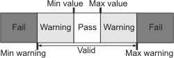
Sets the maximum acceptable value for the geometric tolerance MIL uses to validate the feature or the relationship between multiple features. INQ (more details...) |
||||||||||||||||||||||||||||||||||||||
| M_DEFAULT |
Specifies the default value; the default value is 0.0. |
||||||||||||||||||||||||||||||||||||||
| Value |
Specifies the maximum value. |
||||||||||||||||||||||||||||||||||||||
|
M_VALUE_MIN |
Sets the minimum value for a geometric tolerance to have a valid status. INQ (more details...) |
||||||||||||||||||||||||||||||||||||||
| M_DEFAULT |
Specifies the default value; the default value is 0.0. |
||||||||||||||||||||||||||||||||||||||
| Value |
Specifies the minimum value. |
||||||||||||||||||||||||||||||||||||||
|
M_VALUE_WARNING_MAX |
Sets the maximum warning value for a geometric tolerance to have a valid status. INQ (more details...) |
||||||||||||||||||||||||||||||||||||||
| M_DEFAULT |
Specifies the default value; the default value is 0.0. |
||||||||||||||||||||||||||||||||||||||
| Value |
Specifies the maximum warning value. |
||||||||||||||||||||||||||||||||||||||
|
M_VALUE_WARNING_MIN |
Sets the minimum warning value for a geometric tolerance to have a valid status. INQ (more details...) |
||||||||||||||||||||||||||||||||||||||
| M_DEFAULT |
Specifies the default value; the default value is 0.0. |
||||||||||||||||||||||||||||||||||||||
| Value |
Specifies the minimum warning value. |
||||||||||||||||||||||||||||||||||||||
The following ControlType and corresponding ControlValue parameter settings are used to control features and geometric tolerances of a metrology context. For controlling features, the LabelOrIndex parameter can be set to M_GLOBAL_FRAME or one or all features. For controlling geometric tolerances, the LabelOrIndex parameter can be set to one or all tolerances. The MetId parameter must be set to a metrology context.
|
For controlling features or geometric
tolerances |
|||||||||||||||||||||||||||||||||||||||
| ControlType |
Description
|
||||||||||||||||||||||||||||||||||||||
| ControlValue | |||||||||||||||||||||||||||||||||||||||
|
M_ANGLE |
Sets the angle used to construct a feature or define a tolerance, when applicable. INQ (more details...) |
||||||||||||||||||||||||||||||||||||||
| M_DEFAULT |
Specifies the default value; the default value is 0.0°. |
||||||||||||||||||||||||||||||||||||||
| Value |
Specifies the angle. (more details...) |
||||||||||||||||||||||||||||||||||||||
|
M_DRAWABLE |
Sets whether the feature or tolerance will be drawn using MmetDraw(). INQ (more details...) |
||||||||||||||||||||||||||||||||||||||
| M_DISABLE |
Specifies that the feature or tolerance will not be drawn. (more details...) |
||||||||||||||||||||||||||||||||||||||
| M_ENABLE |
Specifies that the feature or tolerance will be drawn. (more details...) |
||||||||||||||||||||||||||||||||||||||
The following ControlType and corresponding ControlValue parameter settings are used to control the transformation applied to a clone-type feature. (MmetAddFeature() with M_CLONE_FEATURE). For example, using M_CLONE_SCALE, you can clone a circle feature at twice its size. For controlling clone transformations, you must set the LabelOrIndex parameter to an existing clone-type feature label or index using M_FEATURE_LABEL() or M_FEATURE_INDEX(). The MetId parameter must be set to a metrology context.
|
For controlling clone
transformations |
|||||||||||||||||||||||||||||||||||||||
| ControlType |
Description
|
||||||||||||||||||||||||||||||||||||||
| ControlValue | |||||||||||||||||||||||||||||||||||||||
|
M_CLONE_ANGLE |
Sets the rotation angle, in the counterclockwise direction, that will be used when cloning the feature. INQ (more details...) |
||||||||||||||||||||||||||||||||||||||
| M_DEFAULT |
Specifies the default value; the default value is 0.0°. |
||||||||||||||||||||||||||||||||||||||
|
0.0 <= Value <= 360.0 |
Specifies the angle, in degrees. |
||||||||||||||||||||||||||||||||||||||
|
M_CLONE_OFFSET_X |
Sets the translation value, in the X-direction, that will be used when cloning the feature. INQ (more details...) |
||||||||||||||||||||||||||||||||||||||
| M_DEFAULT |
Specifies the default value; the default value is 0.0 pixels. |
||||||||||||||||||||||||||||||||||||||
| Value |
Specifies the X-offset for the cloned feature, in pixel or world units. |
||||||||||||||||||||||||||||||||||||||
|
M_CLONE_OFFSET_Y |
Sets the translation value, in the Y-direction, that will be used when cloning the feature. INQ (more details...) |
||||||||||||||||||||||||||||||||||||||
| M_DEFAULT |
Specifies the default value; the default value is 0.0 pixels. |
||||||||||||||||||||||||||||||||||||||
| Value |
Specifies the Y-offset for the cloned feature, in pixel or world units. |
||||||||||||||||||||||||||||||||||||||
|
M_CLONE_SCALE |
Sets the scale factor, that will be used when cloning the feature. INQ (more details...) |
||||||||||||||||||||||||||||||||||||||
| M_DEFAULT |
Specifies the default value; the default value is 1.0. |
||||||||||||||||||||||||||||||||||||||
| Value > 0.0 |
Specifies the scale factor. |
||||||||||||||||||||||||||||||||||||||
The following ControlType and corresponding ControlValue parameter settings are used to control the results calculated and stored in a metrology result buffer. For controlling results, the LabelOrIndex parameter must be set to M_GENERAL. The MetId parameter must be set to a metrology result buffer.
|
For controlling
results |
|||||||||||||||||||||||||||||||||||||||
| ControlType |
Description
|
||||||||||||||||||||||||||||||||||||||
| ControlValue | |||||||||||||||||||||||||||||||||||||||
|
M_OUTPUT_FRAME |
Sets the output reference frame that MIL uses to return feature results. INQ (more details...) |
||||||||||||||||||||||||||||||||||||||
| M_DEFAULT |
Same as M_GLOBAL_FRAME. |
||||||||||||||||||||||||||||||||||||||
| M_GLOBAL_FRAME |
Specifies that MIL returns feature results relative to the origin of the global frame. (more details...) |
||||||||||||||||||||||||||||||||||||||
| M_IMAGE_FRAME |
Specifies that MIL returns feature results relative to the origin of the target image's reference frame. (more details...) |
||||||||||||||||||||||||||||||||||||||
| M_REFERENCE_FRAME |
Specifies that MIL returns feature results relative to the reference frame of each feature. (more details...) |
||||||||||||||||||||||||||||||||||||||
| Label |
Specifies the label of an existing local frame feature to use to return feature results. |
||||||||||||||||||||||||||||||||||||||
|
M_RESULT_OUTPUT_UNITS |
Sets whether to return results in pixels or world units. INQ (more details...) |
||||||||||||||||||||||||||||||||||||||
| M_DEFAULT |
Same as M_ACCORDING_TO_CALIBRATION. |
||||||||||||||||||||||||||||||||||||||
| M_ACCORDING_TO_CALIBRATION |
Specifies that results are returned in world units if the result was calculated on an image associated with a calibration context; otherwise, specifies that results are returned in pixel units. |
||||||||||||||||||||||||||||||||||||||
| M_PIXEL |
Specifies that results are returned in pixel units, with respect to the pixel coordinate system. |
||||||||||||||||||||||||||||||||||||||
| M_WORLD |
Specifies that results are returned in world units, with respect to the relative coordinate system. (more details...) |
||||||||||||||||||||||||||||||||||||||
The following ControlType and corresponding ControlValue parameter settings are used to delete features and tolerances from the context. The LabelOrIndex parameter can be set to one of the following: M_ALL_FEATURES, M_ALL_TOLERANCES, an existing feature label or index using M_FEATURE_LABEL() or M_FEATURE_LABEL(), or an existing tolerance label or index using M_TOLERANCE_LABEL() or M_TOLERANCE_INDEX(). The MetId parameter must be set to a metrology context.
|
For deleting features and
tolerances |
|||||||||||||||||||||||||||||||||||||||
| ControlType |
Description
|
||||||||||||||||||||||||||||||||||||||
| ControlValue | |||||||||||||||||||||||||||||||||||||||
|
M_DELETE |
Deletes a specific feature, a specific tolerance, all features, or all tolerances. (more details...) |
||||||||||||||||||||||||||||||||||||||
| M_DEFAULT |
Same as M_NULL. |
||||||||||||||||||||||||||||||||||||||
| M_NULL |
Deletes a specific feature, a specific tolerance, all features, or all tolerances. |
||||||||||||||||||||||||||||||||||||||
|
void MmetControlInt64
(MIL_ID MetId,
MIL_INT LabelOrIndex,
MIL_INT64 ControlType,
MIL_INT64 ControlValue)
Parameters
MetId See MetId of the main function for a description. LabelOrIndex See LabelOrIndex of the main function for a description. ControlType See ControlType of the main function for a description. ControlValue See ControlValue of the main function for a description. |
| Header | Include mil.h. |
| Library | Use mil.lib; milmetrol.lib. |
| DLL | Requires mil.dll; milmetrol.dll. |