Moving the relative coordinate system to account for height
When using 3D calibration modes, the Z-coordinate of the relative and absolute coordinate system can have a physical meaning in terms of a height, even if all points in an image are assumed to be on the same plane (even if that plane is slanted) and all results (except those from the Camera calibration module and the 3D reconstruction module) are returned to a 2D coordinate system. For example, the area of an object in real-world units will be different if the relative coordinate system is moved to a different height. Consequently, it is important to consider where the absolute coordinate system is placed and how measurements are taken.
Measuring two features displaced by a known height
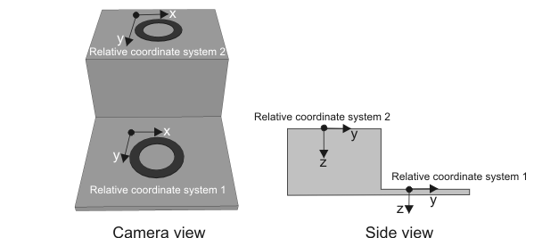
All results are returned in the relative coordinate system, so you must move it to the location where you need to measure. However, two objects can be located in different planes and suffer from perspective distortion. Although the calibration context will account for two dimensional perspective distortion in a single plane, it cannot account for a difference in height as well. For example, two identical rings sitting on boxes of different heights will appear to have a different size and perhaps shape from the camera's view point. To ensure that measurements are comparable, the relative coordinate system can be moved to the correct plane before a measurement is taken for each object.
To displace the relative coordinate system, perform the following:
-
Determine the location of the object to be measured.
-
Displace the relative coordinate system to its corresponding plane using McalSetCoordinateSystem(). For information, see the Moving coordinate systems to reflect camera setup changes section of Chapter 25: Calibrating your camera setup.
-
Measure the feature(s) of interest.
-
Repeat steps 1 through 3 for each object to be measured that is on a different plane.
The following images depict two rings sitting on boxes of different height, from the camera and side view respectively.
Note that if your object is located in a plane which is on a slant, the relative coordinate system must be positioned on that slant.
Accounting for thickness of calibration grids in 3D setups
Even when using a 3D-based calibration context, you can use grids to provide calibration points. However, the grid used in the calibration has a certain thickness. Depending on your application, you should correct for this thickness and ensure that the XY (Z=0) plane of the absolute coordinate system is well placed. This is important if you are using the calibration context with a 3D reconstruction setup where measurements in height will be taken.
To account for the thickness of the calibration grid, specify the height of the grid using McalGrid() with GridOffsetZ.