McalGrid
| MIL_ID CalibrationId, | //in |
| MIL_ID SrcImageBufId, | //in |
| MIL_DOUBLE GridOffsetX, | //in |
| MIL_DOUBLE GridOffsetY, | //in |
| MIL_DOUBLE GridOffsetZ, | //in |
| MIL_INT RowNumber, | //in |
| MIL_INT ColumnNumber, | //in |
| MIL_DOUBLE RowSpacing, | //in |
| MIL_DOUBLE ColumnSpacing, | //in |
| MIL_INT64 Operation, | //in |
| MIL_INT64 GridType | //in |
This function uses an image of a user-defined grid of circles or squares and the world description of this grid to establish calibration points and calibrate your camera setup. The mapping is stored with the specified calibration context. The specified calibration context determines the calibration mode used.
MIL is distributed with four different calibration grids that you can print and use: ChessboardCalibrationGrid_15x16_Letter.pdf, ChessboardCalibrationGrid_18x22_Letter.pdf, CircleCalibrationGrid_15x16_Letter.pdf, CircleCalibrationGrid_18x22_Letter.pdf. These files are located in the Matrox Imaging\Images directory. Each file includes the world description of the grid.
Typically, you specify the world description of the grid in the absolute coordinate system. However, for 3D-based calibration modes (M_TSAI_BASED or M_3D_ROBOTICS), it is possible to use a grid that is not in the XY-plane (Z=0) of the absolute coordinate system. In this case, use the GridOffsetZ parameter to specify the height of the grid being used.
When working in M_3D_ROBOTICS calibration mode, you must call this function at least three times to accumulate data with different images and orientations (each time with M_ACCUMULATE) before calling this function a fourth time (with M_FULL_CALIBRATION and no image) to perform the full calibration. Before each data accumulation call, you must change the position and orientation of the tool holding the camera with respect to the robot base. More specifically, you must rotate the tool along at least two non-parallel axes. You must also use McalSetCoordinateSystem() to set the position of the tool coordinate system with respect to the robot base coordinate system before each of these calls. You must call McalGrid() with M_ACCUMULATE more than three times before performing a full calibration improves the accuracy of your calibration.
You can inquire about the pixel coordinates and associated real-world coordinates of each calibration point of one particular call using McalInquireSingle().
For 3D-based calibration modes, McalGrid() performs two types of calculations. It calculates the camera's internal attributes, and it calculates the orientation and distance between the camera and camera calibration plane. Initially, the latter is used to set the camera coordinate system. If you move the camera or the grid (not both), you can have McalGrid() recalculate only the orientation and distance between them. In this case, depending on what you moved, you can specify that McalGrid() displace either the camera coordinate system or the relative coordinate system, using M_DISPLACE_CAMERA_COORD or M_DISPLACE_RELATIVE_COORD, respectively. When using M_DISPLACE_RELATIVE_COORD, the camera calibration plane is considered to be the XY-plane of the relative coordinate system, regardless of the M_CALIBRATION_PLANE setting.
Also, for 3D-based calibration modes, a successful call to McalGrid() with M_FULL_CALIBRATION creates a rigid link between the camera coordinate system and the tool coordinate system. This link ensures that moving either the tool or the camera coordinate system will affect both. This link can be broken using McalControl() with M_LINK_TOOL_AND_CAMERA.
Note that the internal attributes calculated for the camera are not those of the physical camera, but those of the ideal pinhole-camera used to model the physical camera.
After calling McalGrid(), you can inquire about the success of the calibration using McalInquire() with M_CALIBRATION_STATUS. Also, you can inquire about the pixel coordinates and associated real-world coordinates of each calibration point using McalInquire() with M_CALIBRATION_IMAGE_POINTS_X, M_CALIBRATION_IMAGE_POINTS_Y, M_CALIBRATION_WORLD_POINTS_X, M_CALIBRATION_WORLD_POINTS_Y, and M_CALIBRATION_WORLD_POINTS_Z. These coordinates correspond to the center of circles in a circle grid or to points connecting four corners in a chessboard grid.
When the image of the calibration grid is rotated, for instance when the image of the grid has been taken by a second camera at a different angle, you might need to specify where the top-left corner of the real-world grid is in the rotated image. This is done using McalGrid() set to M_GRID_CORNER_HINT_X and M_GRID_CORNER_HINT_Y. Note that RowNumber and ColumnNumber specify the number of rows and columns of the calibration grid as it is in the world, and not as it appears in the rotated image.
For more information on performing camera calibration, see the Steps to performing a calibration section of Chapter 25: Calibrating your camera setup.
Specifies the identifier of the image buffer containing the grid. It must be an 8- or 16-bit unsigned buffer, with 1 or 3 bands.
This image buffer must not have a region of interest (ROI) associated with it. Using an image buffer with an ROI will cause an error.
Note that the source image used for calibration is automatically calibrated after a successful call to McalGrid() with M_FULL_CALIBRATION.
When performing a M_FULL_CALIBRATION operation in M_3D_ROBOTICS calibration mode, set this parameter to M_NULL.
Specifies the X-position of the top-left circle of the calibration grid of circles or the top-left point connecting four squares in a chessboard grid. Specify its X-position in the calibration-plane coordinate system, in world-units.
When performing a M_FULL_CALIBRATION operation in M_3D_ROBOTICS calibration mode, set this parameter to M_NULL.
Specifies the Y-position of the top-left circle of the calibration grid of circles or the top-left point connecting four squares in a chessboard grid. Specify its Y-position in the calibration-plane coordinate system in, world-units.
When performing a M_FULL_CALIBRATION operation in M_3D_ROBOTICS calibration mode, set this parameter to M_NULL.
Specifies the Z-position of the top-left circle of the calibration grid of circles or the top-left point connecting four squares in a chessboard grid. Specify its Z-position in the calibration-plane coordinate system in, world-units.
For 2D-based calibration modes, or when performing a M_FULL_CALIBRATION operation in M_3D_ROBOTICS calibration mode, set this parameter to M_NULL.
Specifies the number of rows in the calibration grid. The minimum number of rows is 2 when GridType is set to M_CIRCLE_GRID and 3 when set to M_CHESSBOARD_GRID.
For M_UNIFORM_TRANSFORMATION, M_LINEAR_INTERPOLATION, and M_PERSPECTIVE_TRANSFORMATION calibration modes, the minimum number of grid points required is 4. For M_TSAI_BASED and M_3D_ROBOTICS calibration modes, you must provide a grid that contains at least 6 grid points, even though the minimum number of rows and the minimum number of columns are both 2. Accuracy increases with the number of points.
For 3D-based calibration contexts (M_TSAI_BASED and M_3D_ROBOTICS calibration modes), and performing a M_DISPLACE_CAMERA_COORD or M_DISPLACE_RELATIVE_COORD operation, the minimum number of grid points required is 4.
When performing a M_FULL_CALIBRATION operation in M_3D_ROBOTICS calibration mode, set this parameter to M_NULL.
Note that in the case of a rotated image of a rectangular calibration grid, you must specify the number of rows of the real-world grid and not the number of rows as it appears in the rotated image.
Specifies the number of columns in the calibration grid. The minimum number of columns is 2 when GridType is set to M_CIRCLE_GRID and 3 when set to M_CHESSBOARD_GRID.
When performing a M_FULL_CALIBRATION operation in M_3D_ROBOTICS calibration mode, set this parameter to M_NULL.
Note that in the case of a rotated image of a rectangular calibration grid, you must specify the number of columns of the real-world grid and not the number of columns as it appears in the rotated image.
Specifies the number of world units between rows.
When performing a M_FULL_CALIBRATION operation in M_3D_ROBOTICS calibration mode, set this parameter to M_NULL.
Specifies the number of world units between columns.
When performing a M_FULL_CALIBRATION operation in M_3D_ROBOTICS calibration mode, set this parameter to M_NULL.
Specifies the calibration operation to perform. This parameter must be set to one of the following values:
 For specifying the calibration
operation
For specifying the calibration
operation |
|||||||||||||||||||||||||||||||||||||||
  Value Value |
Description
|
||||||||||||||||||||||||||||||||||||||
| M_DEFAULT |
Same as M_FULL_CALIBRATION. |
||||||||||||||||||||||||||||||||||||||
| M_ACCUMULATE |
Calculates only the position of the calibration points and stores them in the calibration context. (more details...) |
||||||||||||||||||||||||||||||||||||||
| M_DISPLACE_CAMERA_COORD |
Calculates only the position and orientation between the camera and the camera calibration plane, and displaces the camera coordinate system accordingly. (more details...) |
||||||||||||||||||||||||||||||||||||||
| M_DISPLACE_RELATIVE_COORD |
Calculates only the position and orientation between the camera and the camera calibration plane, and displaces the relative coordinate system accordingly. (more details...) |
||||||||||||||||||||||||||||||||||||||
| M_FULL_CALIBRATION |
Performs a full calibration. (more details...) |
||||||||||||||||||||||||||||||||||||||
Specifies the type of grid used. This parameter must be set to one of the following values:
|
For specifying the type of
grid |
|||||||||||||||||||||||||||||||||||||||
| Value |
Description
|
||||||||||||||||||||||||||||||||||||||
| M_DEFAULT |
Same as M_CIRCLE_GRID. |
||||||||||||||||||||||||||||||||||||||
| M_CHESSBOARD_GRID + |
Specifies a chessboard grid. The number of rows and columns represents the number of corners horizontally and vertically. A corner is the intersection of 4 cells, meaning that the corners on the perimeter do not count. Note that, for a chessboard grid type, the number of rows and the number of columns must be at least 3. The following is an example of a valid 4x4 chessboard grid. 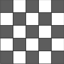
Specifies a chessboard grid. (more details...) |
||||||||||||||||||||||||||||||||||||||
| M_CIRCLE_GRID + |
Specifies a grid of circles. (more details...) |
||||||||||||||||||||||||||||||||||||||
You can add one of the following values to the above-mentioned values to set the orientation of the Y-axis.
These combination values are not supported if using M_UNIFORM_TRANSFORMATION calibration mode.
|
For specifying the orientation of the
Y-axis INQ |
|||||||||||||||||||||||||||||||||||||||
| Combination value |
Description
|
||||||||||||||||||||||||||||||||||||||
| M_Y_AXIS_DOWN |
Orients the positive Y-axis along the first column of circles in a grid of circles, or along square corners in a chessboard grid. (more details...) |
||||||||||||||||||||||||||||||||||||||
| M_Y_AXIS_UP |
Orients the positive Y-axis along the first column of circles in a grid of circles, or along square corners in a chessboard grid. (more details...) |
||||||||||||||||||||||||||||||||||||||
You can add the following value to the above-mentioned values to set the speed of calibration.
|
For increasing the speed of
calibration |
|||||||||||||||||||||||||||||||||||||||
| Combination value |
Description
|
||||||||||||||||||||||||||||||||||||||
| M_FAST |
Speeds up the time it takes to perform the calibration by using a faster calibration algorithm. (more details...) |
||||||||||||||||||||||||||||||||||||||
| Header | Include mil.h. |
| Library | Use mil.lib; milcal.lib. |
| DLL | Requires mil.dll; milcal.dll. |