Partially corrected depth maps
- See also

 Availability
 Previous
- Next

-
Allocate a 3D reconstruction context using M3dmapAlloc() with M_DEPTH_CORRECTION.
-
Allocate a 3D reconstruction calibration result buffer using M3dmapAllocResult() with M_LASER_CALIBRATION_DATA.
-
Grab an image of a laser line on a planar object that has a known height. The image of a laser line on an object at a known height is called a reference plane.
-
Specify the gray value associated with the height of the reference plane, using M3dmapControl() with M_CORRECTED_DEPTH.
-
Use M3dmapAddScan() to extract the laser line information from the grabbed image and add this information to the 3D reconstruction calibration result buffer. For other methods of providing the laser line data, see the Using 3D cameras that output uncorrected depth maps section earlier in this chapter.
If, after calling M3dmapAddScan(), but before calling M3dmapCalibrate(), you need to discard the last scan added (for example, as the result of a diagnosis using M3dmapDraw() with M_DRAW_PEAKS_LAST), it is possible to do so by calling M3dmapClear() with M_REMOVE_LAST_SCAN.
-
Repeat steps 3 to 5 for every reference plane that you want to use to calibrate your 3D reconstruction setup. You can calibrate using only a single reference plane; however, your results will be more accurate if you calibrate using more plane heights. Note that you can use the surface on which the object is resting as a reference plane.
The size and depth of the source image buffer containing the laser lines must not change when making multiple calls to M3dmapAddScan() and you must use the same destination result buffer.
-
Call M3dmapCalibrate() with the 3D reconstruction context, calibration result buffer, and camera calibration context.
-
Use M3dmapInquire() with M_CALIBRATION_STATUS, while specifying the 3D reconstruction context, to ensure that the calibration of the 3D reconstruction setup has been successfully performed.
-
Free the 3D reconstruction calibration result buffer using M3dmapFree().
-
Allocate a new 3D reconstruction result buffer to hold the partially corrected depth map, using M3dmapAllocResult() with M_DEPTH_CORRECTED_DATA.
-
Grab a series of images of an object as it passes through the laser plane. For each image, extract the laser line information from the image and add the data to the M_DEPTH_CORRECTED_DATA 3D reconstruction result buffer, using M3dmapAddScan().
The 3D reconstruction result buffer now contains a partially corrected depth map.
-
Copy the depth map to an image buffer using M3dmapCopyResult() with M_PARTIALLY_CORRECTED_DEPTH_MAP.
-
If required, obtain additional information about the depth map using M3dmapGetResult().
-
Free all your allocated objects using M3dmapFree() and McalFree().
-
The X-size of the depth map image buffer must be at least the X-size of the laser line images, if MimControl() with M_SCAN_LANE_DIRECTION is set to M_VERTICAL. If M_SCAN_LANE_DIRECTION is set to M_HORIZONTAL, the X-size of the depth map image buffer must be at least the Y-size of the laser line images.

Note that to inquire the scan lane direction, you must first call M3dmapInquire() with M_LOCATE_PEAK_1D_CONTEXT_ID to acquire the internal image processing context, then use it on MimInquire() with M_SCAN_LANE_DIRECTION.
-
The required Y-size of the depth map image buffer depends on the number of laser scan lines stored in the result buffer. As such, the Y-size of the depth map image buffer must be bigger than either the number of laser lines extracted or the value of M3dmapControl() with M_MAX_FRAMES, whichever is smaller.
-
The depth map image buffer must be an 8-bit or 16-bit unsigned buffer.
-
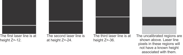
The region(s) where the laser line can appear in subsequent laser line images (M_DRAW_REGION_VALID). This operation draws all pixels that have a valid height associated with them.

-
The region(s) where the laser line cannot appear in subsequent laser line images, because the images are not calibrated in this region (M_DRAW_REGION_UNCALIBRATED). This operation draws all pixels which are not associated with a valid height, because they are found outside the region bounded by the calibration laser lines.
-
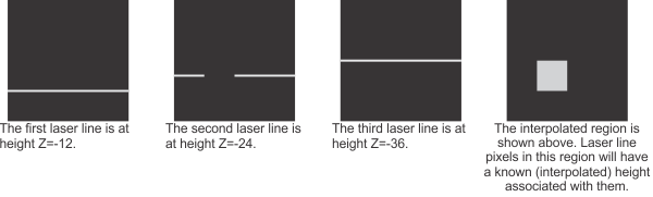
The region(s) where the laser line can appear in subsequent laser line images, but where results are less accurate due to interpolation (M_DRAW_REGION_INTERPOLATED). This operation draws all pixels that are calibrated by interpolation, due to missing data (gaps) in the calibration laser lines. These pixels have a valid height associated with them, but the height is less accurate than if there had been no missing data in the calibration laser lines.
-
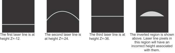
The region(s) in subsequent laser line images where the laser line is interpreted incorrectly due to an inversion during 3D reconstruction calibration (M_DRAW_REGION_INVERTED). An inversion occurs when a calibration laser line specified to be at a lower height is found above a calibration laser line specified to be at a higher height. For example, if the laser line representing a height of 24 is found above the laser line representing a height of 36, the region between these laser lines is inverted. These pixels have a valid height associated with them; however, they will be incorrect. Within an inverted region, pixels that should be associated with a height greater than that of pixels on the previous row (or column, depending on the scan orientation) are instead associated with lower heights.
-
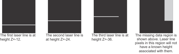
The region(s) where the laser line cannot appear in subsequent laser line images because of missing data in the calibration laser lines, and where the pixels cannot be calibrated by interpolation (M_DRAW_REGION_MISSING_DATA). This operation draws all pixels that are not associated with a valid height because of missing data (gaps) in the calibration laser lines and that cannot be calibrated by interpolation.
Depth maps come in three types: uncorrected, partially corrected, and fully corrected. Partially corrected depth maps are corrected (calibrated) for depth, but not for camera distortion. Their pixel intensities correspond to the heights of the scanned objects, but their pixel coordinates do not correspond to the real-world coordinates of scanned objects.
Generating a partially corrected depth map is similar to generating a fully corrected depth map, with a few exceptions. To generate a partially corrected depth map, you must allocate a M_DEPTH_CORRECTION 3D reconstruction context. Once this is done, you must calibrate your 3D reconstruction context for depth; however, to generate a partially corrected depth map, you don't need to calibrate the camera. Once the setup has been calibrated and tested, you must allocate a 3D reconstruction result buffer of type M_DEPTH_CORRECTED_DATA for runtime scanning.

Note that a partially corrected depth map can only be generated from a single camera-laser pair.
Calibrating for a partially corrected depth map
To generate a partially corrected depth map, you must first have a properly configured 3D reconstruction setup, which includes the physical setup (such as camera placement and laser line setup) and can include adjusting MIL settings. For more information, see the Configuring the laser line profiling setup section earlier in this chapter. Once this is complete, you must calibrate the 3D reconstruction context for depth as follows. Note that the following procedure will calibrate the 3D setup for depth and does not calibrate the camera, which is unnecessary for partial depth maps.
For heights between those defined during 3D reconstruction calibration, the module will perform linear interpolation.
You can inspect the 3D reconstruction calibration state of the pixels once the 3D context has been calibrated. See the Inspecting the calibration state of a 3D reconstruction context subsection of this section.
The following code snippet is an example of the steps required to calibrate a 3D reconstruction setup that can generate a partially corrected depth map.
/* Allocate 3dmap objects. */
M3dmapAlloc(MilSystemId, M_LASER, M_DEPTH_CORRECTION, &LaserId);
M3dmapAllocResult(MilSystemId, M_LASER_CALIBRATION_DATA, M_DEFAULT, &ScanId);

/* Inquire internal locate peak Mim context Id, if peak detection needs configuration. */
M3dmapInquire(LaserId, M_DEFAULT, M_LOCATE_PEAK_1D_CONTEXT_ID, &MilPeakLocatorId);

/* Set settings with M3dmapControl() and MimControl(), if needed. */
/* ... */

for (n = 0; n < NB_CALIBRATION_IMAGES; n++)
   {
   /* Grab next image. */
   /* MbufLoad() can also be used to load an image. */
   MdigGrab(DigId, MilImageId);

   /* Set desired corrected depth of next reference plane. */
   /* CorrectedDepths is an array which has been filled with known depths. */
   M3dmapControl(LaserId, M_DEFAULT, M_CORRECTED_DEPTH, CorrectedDepths[n]);

   /* Analyze the image to extract laser line. */
   M3dmapAddScan(LaserId, ScanId, MilImageId, M_NULL, M_NULL, M_DEFAULT, M_DEFAULT);
   }

/* Calibrate the laser profiling context using reference planes of known heights. */
M3dmapCalibrate(LaserId, ScanId, M_NULL, M_DEFAULT);
Generating a partially corrected depth map
Once your M_DEPTH_CORRECTED_DATA 3D reconstruction context has been calibrated, you are ready for runtime scanning. The following steps provide a basic methodology for runtime scanning using the MIL 3D Reconstruction module.
In M_DEPTH_CORRECTION 3D reconstruction mode, M3dmapCopyResult() with M_PARTIALLY_CORRECTED_DEPTH_MAP generates a partially corrected depth map and tries to store the entire depth map in the specified image buffer. As such, there are restrictions on the dimensions of the image buffer used to store the generated depth map.
Note that you can call M3dmapGetResult() with M_PARTIALLY_CORRECTED_DEPTH_MAP_SIZE_X or M_PARTIALLY_CORRECTED_DEPTH_MAP_SIZE_Y to determine the minimum required X-size and Y-size of the depth map image buffer, respectively.
The following code snippet shows how to generate a partially corrected depth map.
/* Retrieve the expected SizeX and SizeY of the depth map and type of the intensity map.*/
M3dmapGetResult(ScanId, M_DEFAULT,
   M_PARTIALLY_CORRECTED_DEPTH_MAP_SIZE_X+M_TYPE_MIL_INT, &SizeX);
M3dmapGetResult(ScanId, M_DEFAULT,
   M_PARTIALLY_CORRECTED_DEPTH_MAP_SIZE_Y+M_TYPE_MIL_INT, &SizeY);
M3dmapGetResult(ScanId, M_DEFAULT,
   M_INTENSITY_MAP_BUFFER_TYPE+M_TYPE_MIL_INT, &IntensityMapType);

/* Allocate image buffers for the depth map and intensity map. */
MbufAlloc2d(MilSystemId, SizeX, SizeY, 16+M_UNSIGNED,
                        M_IMAGE+M_PROC, &DepthMapImageId);
MbufAlloc2d(MilSystemId, SizeX, SizeY, IntensityMapType,
                        M_IMAGE+M_PROC, &IntensityMapImageId);

/* Generate the depth map and intensity map.  */
M3dmapCopyResult(ScanId, M_DEFAULT, DepthMapImageId, M_PARTIALLY_CORRECTED_DEPTH_MAP, M_DEFAULT);
M3dmapCopyResult(ScanId, M_DEFAULT, IntensityMapImageId, M_INTENSITY_MAP, M_DEFAULT);
Inspecting the calibration state of a 3D reconstruction context
After calibrating a 3D reconstruction context in M_DEPTH_CORRECTION mode, it is possible to inspect the 3D reconstruction calibration state of each pixel in subsequent laser line images, using either M3dmapDraw() or M3dmapInquire(). By doing so, you can determine whether the pixels are well calibrated, or if they are interpolated, inverted, or left uncalibrated due to missing data. Unless otherwise specified, if you have regions with missing or invalid data, you should probably recalibrate your 3D reconstruction setup for depth.
Using M3dmapDraw(), you can draw:
The following image illustrates how to use M_DRAW_REGION_... to diagnose your calibration of the laser line image.
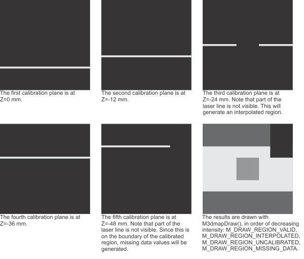
With M3dmapInquire(), it is possible to obtain this 3D reconstruction calibration information as statistics. Based on the number of laser line calibration planes grabbed during 3D reconstruction calibration, you can retrieve an array detailing the number of missing depth values (data points) or inversions per column (using M_NUMBER_OF_MISSING_DATA_PER_COLUMN or M_NUMBER_OF_INVERSIONS_PER_COLUMN, respectively). For example, in the image above, 5 depth maps planes were grabbed during 3D reconstructions calibration and therefore the number of missing data points or inversions can be any whole number from 0 to 5 for every column. Alternatively, you can retrieve the number of columns with missing data points or with inversions (using M_NUMBER_OF_COLUMNS_WITH_MISSING_DATA or M_NUMBER_OF_COLUMNS_WITH_INVERSIONS, respectively).