Configuring the laser line profiling setup
- See also

 Availability
 Previous
- Next

-
The laser line, which is the intersection of the sheet of light (laser plane) and the conveyor, should be perpendicular to the object's motion, as in the image below.

Note that the sheet of light does not have to be perpendicular to the conveyor. When it is not perpendicular to the conveyor, there are extra considerations during 3D reconstruction calibration later.
-
The displacement of the object between each grab of the laser line must be specified. However, the distance between each displacement does not need to be the same; only the direction needs to be the same.
-
Minimum contrast. This is the minimum increase in intensity between the local background and the prospective peak, to be considered a peak. This is set using MimControl() with M_MINIMUM_CONTRAST. If you set the minimum contrast too high, M3dmapAddScan() will not detect the laser line if it is not bright enough compared to its neighborhood. If you set the minimum contrast too low, M3dmapAddScan() might detect a laser line where there is none.
-
Thickness of the laser line. This determines the range of acceptable pixel widths for a peak (laser line). This range is specified using two separate MimControl() control types, M_PEAK_WIDTH_NOMINAL and M_PEAK_WIDTH_DELTA. The former specifies the mean width of the laser line, in pixels; the latter specifies the expected variance. Any peaks that are found that are wider than M_PEAK_WIDTH_NOMINAL + M_PEAK_WIDTH_DELTA, or narrower than M_PEAK_WIDTH_NOMINAL- M_PEAK_WIDTH_DELTA, are rejected.
-
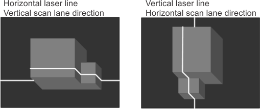
Orientation of the laser line. This determines whether laser line detection is performed vertically or horizontally. If your laser line is horizontal across the image, set MimControl() with M_SCAN_LANE_DIRECTION to M_VERTICAL. If your laser line is vertical across the image, set M_SCAN_LANE_DIRECTION to M_HORIZONTAL.
Images with diagonal laser lines are processed sub-optimally.
-
Allocate a 3D reconstruction result buffer of type M_LASER_CALIBRATION_DATA using M3dmapAllocResult().
-
Grab an image of an object that displaces the laser line. You should choose a typical object that will be scanned under normal runtime conditions. This is especially true if the objects are reflective. It is also important that the environmental conditions, such as ambient lighting, during the test grab are similar to how they will be under typical runtime conditions.
-
Extract the laser line data from the grabbed image using M3dmapAddScan().
-
Draw the extracted laser line using M3dmapDraw() with M_DRAW_PEAKS_LAST.
Confirm that the extracted laser line, which is drawn on the grabbed image, overlaps with the actual laser line in the grabbed image.
-
Additionally, inquire the number of missing data points in the most recently extracted laser line using M3dmapGetResult() with M_NUMBER_OF_MISSING_DATA_LAST_SCAN.
You can clear the extracted line from the result buffer by calling M3dmapClear() with M_REMOVE_LAST_SCAN.
-
If the extracted laser line, drawn with M3dmapDraw(), sufficiently overlaps the actual laser line, and/or the number of missing data points is tolerable, your setup is complete. You can now move on to 3D reconstruction calibration.
If the drawn laser line does not sufficiently overlap the actual laser line, or the missing number of data points is intolerable, change the physical setup and/or your software values. Repeat this testing procedure again.
The main objective of laser line profiling is to establish real-world depth of an object by grabbing and processing sequential images of the object as it passes through a sheet of light or laser plane. If the camera setup has been calibrated, laser line profiling typically results in a cloud of 3D coordinates (cloud of points). To extract the highest quality 3D data, you need to create a proper physical 3D reconstruction setup and configure the 3D reconstruction context (and its internal peak detection image processing context) with the characteristics of the laser line.
Once setup is done, you can further optimize your performance by only processing a subset of the entire grabbed image.
To accelerate prototyping of your laser-based 3D reconstruction setup, you can use the Microsoft Excel file 3D Setup Helper.xls. This file helps you choose an adequate hardware configuration, including the camera, lens, camera angle, and distance from the camera to the object's surface. The file is located in your Matrox Imaging\Tools directory.
Once you have configured the 3D reconstruction physical setup and corresponding context(s), you must then calibrate the depth (height) that the laser line displacement represents. To perform the required 3D reconstruction calibration operations, see the Calibrating to create a point cloud subsection of the Calibrating your 3D reconstruction setup to create a point cloud section later in this chapter.
3D reconstruction physical setup
The physical setup must consider camera placement, laser placement, and conveyor direction, to minimize object occlusion and maximize 3D resolution.
Camera angle requirement
Before starting the 3D reconstruction calibration process of your 3D reconstruction setup, ensure that the angle of the camera is sufficient with respect to the laser so that the camera captures the laser line for each slice of the object. The angle of the camera should be large enough so that small changes in height are enough to cause noticeable changes in the position of the laser lines in the grabbed images. The greater the change in position of the laser line in the grabbed image, the more accurate your results will be.
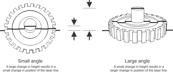
To get very accurate results, you want the camera to be at an angle where the laser line, when located on the highest feature of your object, is located at the top of your laser line image buffer, and when located on the XY plane (Z=0) plane, it is located at the bottom of your laser line image buffer. In general, this means a large angle. However, when your camera angle is large, you potentially increase object occlusion. This is demonstrated in the image above.
The orientation of the camera is also important. Depending on how you orient your camera, the resulting image could have a horizontal, vertical, or diagonal laser line. For optimal results, orient your camera to have a strongly horizontal or vertical laser line. Images with diagonal laser lines are processed sub-optimally.
Sheet of light and conveyor requirements
When scanning an object moving along a conveyor, the object must be moving in a linear motion under the sheet of light. There are a few additional requirements to consider when setting up your 3D reconstruction setup:
3D reconstruction context setup - laser line characteristics
Before performing laser line extraction on an image using M3dmapAddScan(), you can set certain control types in the internal locate peak 1D image processing context of your 3D reconstruction context to specify the characteristics of the laser line. For more information on intensity thresholding, peak detection, and laser line orientation, see the Peak intensity detection and depth maps section of Chapter 5: Specialized image processing.
To set the controls, you must first inquire the identifier of the internal image processing context using M3dmapInquire() with M_LOCATE_PEAK_1D_CONTEXT_ID; then, using MimControl(), you can set the following controls:
Using a 3D camera capable of laser line extraction
The 3D Reconstruction module also lets you use a 3D camera capable of performing laser line extraction directly on the camera. The 3D reconstruction module expects that, in this case, the camera outputs an uncorrected depth map. To pass the 3D camera's uncorrected depth map to the module, you must call M3dmapAddScan() with M_LINE_ALREADY_EXTRACTED and the uncorrected depth map; the function will load the data in the specified result buffer and skip the laser line extraction process. Note that M3dmapAddScan() with M_LINE_ALREADY_EXTRACTED must also be used when you want to pass manually extracted data to M3dmapAddScan() (for example, after processing the laser line image using MimLocatePeak1d()). For more information on performing laser line extraction without the 3D Reconstruction module, see the Using 3D cameras that output uncorrected depth maps section later in this chapter. For information on grabbing from 3D sensors that perform all steps of 3D reconstruction on-board, see the Grabbing from 3D sensors overview section of Chapter 36: Grabbing from 3D sensors.
Inspecting laser line extraction
Once your set up is appropriate and you have specified your laser line characteristics, you should test whether the line can be detected and identify any problems that were present during the extraction process.
To test your physical setup and your software values, perform the following:
Optimizing frame rate, throughput, and processing time using smaller images
Once you have positioned your physical setup and inspected your laser line images, you can further refine your setup to increase the frame rate, increase throughput, and/or decrease processing time, by grabbing, transferring, and/or processing smaller images, respectively.
To increase the frame rate, you can reduce the size of the image you are grabbing; this is typically done directly on the camera, when available. For GigE cameras, you can directly configure the camera's features using the MIL Feature Browser (accessible through Matrox Intellicam or MdigControl() with M_GC_FEATURE_BROWSER).
To increase throughput, you can limit the size of the image your frame grabber saves to memory, using MdigControl() with M_SOURCE_OFFSET_... and M_SOURCE_SIZE_....
To reduce processing time, you can create a child buffer that limits the area of the image buffer that is processed using MbufChild2d(). You can also use a child buffer to split a grabbed image that includes two or more laser lines, so that each child buffer contains a single laser line.
Note that in the case of source offsets and child buffers, you must use the same offset or child buffer for both the images supplied for 3D reconstruction calibration and runtime processing.