Working with non-compliant cameras
- See also

 Availability
 Previous
- Next

If your 3D sensor transmits 3D data in a format defined by an industry standard (such as GigE Vision or GenICam), typically the data will already be correctly formatted for you to use it with MIL. Otherwise, your 3D sensor is non-compliant; the data it transmits is not natively compatible with MIL 3D functions, and you must refer to your 3D sensor manual to determine how 3D information is stored in the transmitted data. You will need to manually prepare this data for use with MIL (possibly using a third-party SDK provided by the device manufacturer). You will also need to set the correct component type and 3D settings for the grabbed data.
Grabbing data from non-compliant 3D sensors
If your non-compliant 3D sensor transmits 3D data using a protocol that MIL can grab (for example, as a standard image stream over GigE Vision), and each frame of data contains only a single type of information (such as point cloud coordinates or a disparity map), you should grab the data directly into a component of a container. You can do this by passing the MIL identifier of the component (previously allocated using MbufAllocComponent()) to MdigGrab() or MdigProcess(). Note that the component must be in a container with the M_GRAB attribute.
If your non-compliant 3D sensor transmits 3D data using a protocol that MIL can grab, and each frame of data contains multiple types of information (such as coordinates, confidence, and intensity), you should grab the data into a standard image buffer. Refer to your camera manual to determine where, and in what format, each type of 3D data is stored in the image. Then, use MbufCreateComponent() to create components for a container with the correct attributes and component type and map them on to these areas in memory.
If your 3D sensor requires you to grab data using a third-party SDK, you need put the grabbed data in a component. Typically, you should do this by copying the values grabbed using the third-party SDK into one or more arrays. You can then pass these arrays, and the MIL identifier of an image buffer component that has the appropriate component type (previously allocated using MbufAllocComponent()) to MbufPut() or MbufPutColor(). If your 3D sensor transmits more than one type of data, you can use this procedure with multiple components to put all of that data in the same container.
If the third-party SDK provides the ability to export 3D data in either the PLY or STL file format, you can load the 3D data from that file into a container using MbufLoad(), MbufRestore(), or MbufImport(). This is useful when performance is not critical (for example, early in application development). Note that point cloud data loaded from a PLY or STL file is typically unorganized. For information on point cloud organization, see the Organized and unorganized point clouds subsection of the Working with points in a point cloud section of Chapter 32: 3D image processing.
When you are working with data grabbed using a third-party SDK, if you require maximum performance and know the exact layout of the data in memory, you can map a component onto that memory using MbufCreateComponent() (if the layout of the data is compatible with MIL). To do this, you must determine the Host address, format, and pitch of the grabbed data. If the third-party SDK continues to manipulate that space in memory after grabbing (for example, by clearing it), you should instead create a buffer on the memory using an MbufCreate...() function, and then copy that buffer to a component using MbufCopyComponent().
Formatting grabbed data for use with MbufConvert3d
Typically, if you need to manually prepare the data transmitted by your 3D sensor to a format supported by MIL, you should first determine which M_3D_REPRESENTATION most closely resembles the structure of the transmitted data. You must then set the M_3D_REPRESENTATION setting of the range or disparity component to this value, and perform any additional operations required for your data to fully match this setting. To learn the exact layout of data required by MIL for each 3D representation, see the Layout of data in a component subsection of this section. You must also include confidence information, either stored in a confidence component or in the range or disparity component itself (using MbufControlContainer() to set the M_3D_INVALID_DATA_VALUE and M_3D_INVALID_DATA_FLAG settings).
If your 3D sensor is supplied with a third-party SDK, you might find it easier to use that SDK to partially, or completely, format your 3D data before putting it into a component. In other cases, you should put the data in a component immediately and manipulate it using MIL functions (such as MimArith()). The best strategy will depend upon the format in which the data is transmitted, and the functionality provided by the third-party SDK.
Once the grabbed 3D data is stored in a container and correctly formatted for use by MIL, you should convert the container to a format that is 3d-displayable and/or 3d-processable using MbufConvert3d().
Layout of data in a component
MIL expects the data in a component to be laid out in a specific way depending on its component type. Many component types are also related to one another. For example, in a container, the same position in the range component and confidence component should describe information about the same point; therefore, the data in these components must be aligned. For this reason, all 3D components in a 3D container must have the same M_SIZE_X and M_SIZE_Y (aside from the mesh component, which you should typically not access directly).
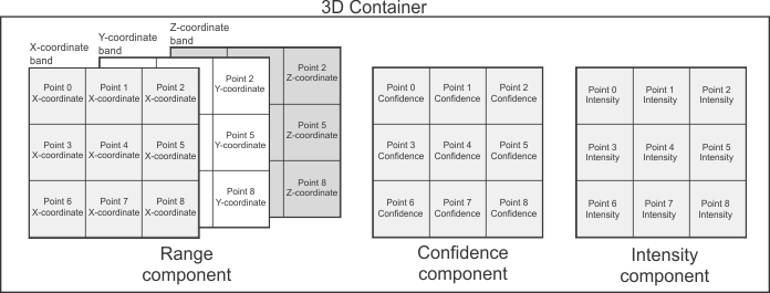
In a point cloud container, no one component stores the points; for example, the range component stores the coordinates of each point, the confidence component stores the confidence of each point, and the intensity component stores the color of each point.
MIL can only process 3D information stored in a container that is M_3D_PROCESSABLE, even if the data in your components is arranged correctly. For more information, see the Preparing a container for display or processing section of Chapter 35: 3D Containers.
The following sections describes how data must be arranged in components you might need to manipulate directly.
Range
An M_COMPONENT_RANGE component is an image buffer that stores the coordinates of points, or a depth map. There are many different ways that this data can be arranged; the exact layout is identified by the component's coordinate system type and 3D representation (set using MbufControlContainer() with M_3D_COORDINATE_SYSTEM_TYPE and M_3D_REPRESENTATION respectively).
MIL only supports range components with M_3D_COORDINATE_SYSTEM_TYPE set to M_CARTESIAN. For this coordinate system type, each pixel-position in the image buffer stores, at most, XYZ-coordinates for a single point. The range component's 3D representation identifies how many bands it must have, and how the XYZ-coordinates are stored in those bands.
All 3D representations, with the exception of M_CALIBRATED_XYZ_UNORGANIZED, are for organized 3D data. This means it is assumed that points close to each other in 3D space are also close to each other in the pixel coordinate system. Typically, disparity components and organized range components should have M_SIZE_Y greater than 1. If your 3D sensor transmits range or disparity data for multiples lines in a single row (for example, multiple profiles from a laser profiler), you can make it organized by splitting that data at a known interval to put it in multiple rows.
In most cases, using MbufConvert3d() with a container that has a range component with an organized 3D representation, but only single row of data, will not produce a correct result. Similarly, specifying an organized 3D representation for 3D data that is unorganized can lead to invalid results when the converted container is passed as a source to MIL processing functions.
The following table describes the required layout for each 3D representation type:
|
3D representation |
Bands |
Description |
|
3 |
X-coordinates are stored in band 0, Y-coordinates are stored in band 1, and Z-coordinates are stored in band 2. |
|
|
3 |
X-coordinates are stored in band 0, Y-coordinates are stored in band 1, and Z-coordinates are stored in band 2. The data is unorganized, meaning that it is stored in a single row, with no implied association between pixel-position and 3D position. Since the coordinates are unorganized, M_SIZE_Y must be 1. |
|
|
3 |
X-coordinates are stored in band 0 and Z-coordinates are stored in band 2 (band 1 is not used). The Y-coordinate for each pixel row is stored in a separate 1-dimensional MIL array buffer that stores one value per row in the component. This M_ARRAY buffer should not be part of the container, and there is no component type for this buffer. For more information, see MbufConvert3d(). |
|
|
3 |
X-coordinates are stored in band 0 and Z-coordinates are stored in band 2 (band 1 is not used). Y-coordinates are stored implicitly by the point's row position in the pixel coordinate system (multiplied by M_3D_SCALE_Y). |
|
|
1 |
Z-coordinates are stored explicitly in the buffer. There are no XY-coordinates in the 3D data stored with this setting. |
|
|
1 |
Z-coordinates are stored explicitly in the buffer. The Y-coordinate for each pixel row is stored in a separate 1-dimensional MIL array buffer that stores one value per row in the component. This M_ARRAY buffer should not be part of the container, and there is no component type for this buffer. For more information, see MbufConvert3d(). There are no X-coordinates in the 3D data stored with this setting. |
|
|
1 |
Z-coordinates are stored explicitly in the buffer. X-coordinates are stored implicitly by the point's column position in the pixel coordinate system (multiplied by M_3D_SCALE_X). The Y-coordinate for each pixel row is stored in a separate 1-dimensional MIL array buffer that stores one value per row in the component. This M_ARRAY buffer should not be part of the container, and there is no component type for this buffer. For more information, see MbufConvert3d(). |
|
|
1 |
Z-coordinates are stored explicitly in the buffer. XY-coordinates are stored implicitly by the point's column and row position in the pixel coordinate system respectively (multiplied by M_3D_SCALE_X and M_3D_SCALE_Y). This is also sometimes referred to as a depth map. |
|
|
1 |
Z-coordinates are stored explicitly in the buffer. These coordinates are not natively calibrated. There are no XY-coordinates in the 3D data stored with this setting. |
Disparity
An M_COMPONENT_DISPARITY component is a 1-band image buffer that stores a disparity map. A disparity map stores the difference in the apparent position of objects in the 2 images produced by a stereoscopic camera. Pixels with higher values indicate that the object shown is further apart in the two images, meaning that the object is closer to the camera.
There are many different ways that this data can be arranged; the exact layout is identified by the component's 3D representation (set using MbufControlContainer() with M_3D_REPRESENTATION).
A disparity map does not explicitly store coordinates, but you can use MbufConvert3d() to convert a container with a disparity map to a point cloud container. Depending on the 3D representation of the disparity component, the Y-coordinates in the resulting range component will be calculated differently.
To correctly convert a container with a disparity component to a point cloud container, you must correctly set the disparity-specific 3D settings (using MbufControlContainer() with control type settings that start with M_3D_DISPARITY_...) for the disparity component. The correct values should be provided by your camera manufacturer.
The following table describes the required layout for each 3D representation type:
|
3D representation |
Description |
|
Y-coordinates are calculated by applying a perspective projection to the image. Typically, this representation type should be used with disparity components that have been generated using areascan cameras. |
|
|
The Y-coordinate for each pixel row is stored in a separate 1-dimensional MIL array buffer that stores one value per row in the component. This M_ARRAY buffer should not be part of the container, and there is no component type for this buffer. For more information, see MbufConvert3d(). Typically, this representation type should only be used with disparity components that have been generated using linescan cameras. |
|
|
Y-coordinates for each pixel are stored implicitly by row index in the pixel coordinate system (multiplied by M_3D_SCALE_Y). Typically, this representation type should only be used with disparity components that have been generated using linescan cameras. |
Confidence
An M_COMPONENT_CONFIDENCE component is a 1-band image buffer that stores confidence information. When a confidence component is part of a 3D container, it stores the probability that each point (or each pixel of a disparity component) is accurate. In MIL, 3D information associated with a confidence value of 0 is considered invalid and is not used by 3D image processing or analysis functions.
The confidence component must have the same M_SIZE_X and M_SIZE_Y as the range or disparity component.
Confidence information can also be indicated within the range or disparity component itself. If an invalid data value is enabled and set (using MbufControlContainer() with M_3D_INVALID_DATA_FLAG and M_3D_INVALID_DATA_VALUE respectively) for the range or disparity component, any point with the Z-coordinate value (or disparity map pixel value) equivalent to the invalid data value will be treated as invalid data when the container is passed to MbufConvert3d().
Intensity
An M_COMPONENT_INTENSITY component is an image buffer that stores a standard 2D image. When an intensity component is part of a 3D container, it stores color information for each point (or each pixel of a disparity component).
The intensity component must have the same M_SIZE_X and M_SIZE_Y as the range or disparity component.
Unlike the other component types, an intensity component is often used to store a photographic image that is not related to the range or disparity component (for example, the image from which the laser line was extracted if the 3D data was acquired using a laser profiler). In this case, the intensity component should not be used as part of a 3D container, because it does not store values for the points in the container.
Reflectance
An M_COMPONENT_REFLECTANCE component is an image buffer that stores a reflectance map. The exact usage of this component varies depending on the 3D sensor used to generate the data. When a reflectance component is part of a 3D container, it stores intensity information for each point (for example, the intensity of the laser line at each point if the 3D data was acquired using a laser profiler). Unlike an intensity component, a reflectance map is typically only used to store values for points, rather than a photographic image.
The reflectance component must have the same M_SIZE_X and M_SIZE_Y as the range or disparity component.
Normals
An M_COMPONENT_NORMALS_MIL component is a 3-band floating-point image buffer that stores a unit vector indicating a direction for each point. Typically, normals indicate what direction is perpendicular to the surface of the object at each point (or, in rare cases, each pixel of a disparity component).
The XYZ-components of the normal vector for each point are stored in band 0,1, and 2 of the buffer, respectively. Each normal vector must be normalized to 1, or be set to 0 in all bands (indicating that there is no normal vector stored for that point).
The normals component must have the same M_SIZE_X and M_SIZE_Y as the range or disparity component.
Examples
The following code snippet shows how to create components on an image buffer containing 3D data, grabbed from a non-compliant 3D sensor:
/* Allocate a buffer for grabbing from 3D sensor that transmits a point cloud as four 515 by 512 blocks */
/* representing X-coordinates, Y-coordinates, Z-coordinates, and reflectance respectively.              */
MIL_ID GrabBuffer = MbufAlloc2d(MilSystem, 512, 2048, 16 + M_UNSIGNED, M_IMAGE + M_GRAB, M_NULL);

/* Calculate the host address of each type of data in the grab buffer. */
void* AddressOfRangeX = (void*)MbufInquire(GrabBuffer, M_HOST_ADDRESS, M_NULL);
void* AddressOfRangeY = (void*)(MbufInquire(GrabBuffer, M_HOST_ADDRESS, M_NULL)
   + MbufInquire(GrabBuffer, M_PITCH_BYTE, M_NULL) * 512);
void* AddressOfRangeZ = (void*)(MbufInquire(GrabBuffer, M_HOST_ADDRESS, M_NULL)
   + MbufInquire(GrabBuffer, M_PITCH_BYTE, M_NULL) * 1024);

void* AddressOfRangeXYZ[3] = { AddressOfRangeX, AddressOfRangeY, AddressOfRangeZ };

void* AddressOfReflectance[] = { (void*)(MbufInquire(GrabBuffer, M_HOST_ADDRESS, M_NULL)
   + MbufInquire(GrabBuffer, M_PITCH_BYTE, M_NULL) * 1536) };

/* Allocate a container that will have components mapped onto the same memory as the grab buffer, */
/* and a container that will store data converted for processing and display.                     */
MIL_ID Grab3dContainer = MbufAllocContainer(MilSystem, M_PROC, M_DEFAULT, M_NULL);
MIL_ID Converted3dContainer = MbufAllocContainer(MilSystem, M_DISP + M_PROC, M_DEFAULT, M_NULL);

/* Create a 3-band range component and a 1-band reflectance component */
/* mapped onto the same memory as the grab buffer.                    */
MIL_ID RangeComponent = MbufCreateComponent(Grab3dContainer, 3, 512, 512, 16 + M_UNSIGNED, M_IMAGE,
   M_HOST_ADDRESS + M_PITCH, M_DEFAULT, AddressOfRangeXYZ,
   M_COMPONENT_RANGE, M_NULL);
MIL_ID ReflectanceComponent = MbufCreateComponent(Grab3dContainer, 1, 512, 512, 16 + M_UNSIGNED, M_IMAGE,
   M_HOST_ADDRESS + M_PITCH, M_DEFAULT, AddressOfReflectance,
   M_COMPONENT_REFLECTANCE, M_NULL);

/* Set the scale settings of the created range component, using settings either provided by the */
/* camera manufacturer or required by the application. The coordinates in the grabbed data will */
/* be multiplied by the scale setting when converted using MbufConvert3D().                     */

MbufControlContainer(Grab3dContainer, M_COMPONENT_RANGE, M_3D_SCALE_X, 0.13f);
MbufControlContainer(Grab3dContainer, M_COMPONENT_RANGE, M_3D_SCALE_Y, 0.13f);
MbufControlContainer(Grab3dContainer, M_COMPONENT_RANGE, M_3D_SCALE_Z, 0.29f);

/* Enable the use of an invalid data value to indicate invalid points in the range component, */
/* and set that value to the invalid data value specified by your camera manufacturer.        */
MbufControlContainer(Grab3dContainer, M_COMPONENT_RANGE, M_3D_INVALID_DATA_FLAG, M_TRUE);
MbufControlContainer(Grab3dContainer, M_COMPONENT_RANGE, M_3D_INVALID_DATA_VALUE, 1984);

while(Grabbing){

   /* Grab new data into the grab buffer. */
   MdigGrab(MILDig, GrabBuffer);

   /* Convert the data in the container on which you created the components to a format supported */
   /* for processing and display. The converted data is stored in automatically allocated         */
   /* components in the destination container.                                                    */
   MbufConvert3d(Grab3dContainer, Converted3dContainer, M_NULL, M_DEFAULT, M_COMPENSATE);
}
The following code snippet shows how to put 3D data (grabbed using a third-party SDK) in the components of a container:
/* Obtain data from a third-party SDK that grabs 3D data in four 515 by 512 blocks       */
/* representing X-coordinates, Y-coordinates, Z-coordinates, and reflectance respectively. */

/* Allocate a container that will store the data obtained from the third-party SDK */
/* and a container that will store data converted for processing and display.      */
MIL_ID Unconverted3dContainer = MbufAllocContainer(MilSystem, M_PROC, M_DEFAULT, M_NULL);
MIL_ID Converted3dContainer = MbufAllocContainer(MilSystem, M_DISP + M_PROC, M_DEFAULT, M_NULL);

/* Allocate a 3-band range component and a 1-band reflectance component  */
/* to store the data so that it can be converted using MbufConvert3d() */
MIL_ID RangeComponent = MbufAllocComponent(Unconverted3dContainer, 3, 512, 512, 16 + M_UNSIGNED
   , M_IMAGE + M_PROC, M_COMPONENT_RANGE, M_NULL);
MIL_ID ReflectanceComponent = MbufAllocComponent(Unconverted3dContainer, 1, 512, 512, 16 + M_UNSIGNED
   , M_IMAGE + M_PROC, M_COMPONENT_INTENSITY, M_NULL);

/* Allocate arrays to store the data grabbed using the third-party SDK */
unsigned short XCoordinates[512 * 512];
unsigned short YCoordinates[512 * 512];
unsigned short ZCoordinates[512 * 512];
unsigned short ReflectanceValues[512 * 512];

/* Set the scale settings of the allocated range component, using settings either provided by the     */
/* camera manufacturer or required by the application. The coordinates in the data obtained from the  */
/* third-party SDK will be multiplied by the scale setting when converted using MbufConvert3d().      */
MbufControlContainer(Unconverted3dContainer, M_COMPONENT_RANGE, M_3D_SCALE_X, 0.13f);
MbufControlContainer(Unconverted3dContainer, M_COMPONENT_RANGE, M_3D_SCALE_Y, 0.13f);
MbufControlContainer(Unconverted3dContainer, M_COMPONENT_RANGE, M_3D_SCALE_Z, 0.29f);

/* Enable the use of an invalid data value to indicate invalid points in the range component.                  */
/* The default invalid data value is 0. You can change the invalid data value using M_3D_INVALID_DATA_VALUE.   */
/* In some cases, it might be simpler to allocate a confidence component and use it to indicate invalid points */
/* in the grabbed data instead.                                                                                */
MbufControlContainer(Unconverted3dContainer, M_COMPONENT_RANGE, M_3D_INVALID_DATA_FLAG, M_TRUE);

/* Grab and convert the data */
while (Grabbing){

   /* Using the third-party SDK, grab the data and copy the appropriate values into each array.                         */
   /* You might need to use the third-party SDK to perform additional operations on the data (such as calibrating it)   */
   /* before copying it into the arrays. Ensure that invalid points have a Z-coordinate of 0, so that these values will */
   /* be marked as invalid data in the converted container.                                                             */

   /* Use MbufPutColor() and MbufPut() to copy the data from the arrays into the previously allocated components */
   MbufPutColor(RangeComponent, 0, M_SINGLE_BAND, XCoordinates);
   MbufPutColor(RangeComponent, 1, M_SINGLE_BAND, YCoordinates);
   MbufPutColor(RangeComponent, 2, M_SINGLE_BAND, ZCoordinates);
   MbufPut(ReflectanceComponent, ReflectanceValues);

   /* Convert the data in the container in which you put the data for processing and display.            */
   /*  The converted data is stored in automatically allocated components in the destination container.  */
   MbufConvert3d(Unconverted3dContainer, Converted3dContainer, M_NULL, M_DEFAULT, M_COMPENSATE);
}