Industrial communication with robots
- See also

 Availability
 Previous
- Next

-
Establish a minimum of three to seven calibration points, depending on the camera calibration mode.
-
Use the robot controller to move the robot to each point and note the coordinates that the robot controller returns for each point.
-
Allocate a camera calibration context using McalAlloc().
-
Use McalList() to map each of the calibration points in pixel coordinates to robot coordinates. For more information about camera calibration using a list of coordinates, see the Calibrating using calibration points from a list section of Chapter 26: Calibrating your camera setup. The direction of the Y-axis and the Z-axis are automatically established from the specified calibration points.
-
Grab an image of the camera calibration grid. This image must be representative of the work area to be calibrated.
-
Allocate a camera calibration context using McalAlloc().
-
Calibrate the camera using McalGrid(). You can use McalGrid() with M_Y_AXIS_COUNTER_CLOCKWISE so that the Y-axis and the Z-axis are pointing up (unlike in the image above). For more information on how to calibrate using a grid, see the Calibrating using calibration points from a grid section of Chapter 26: Calibrating your camera setup.
-
Move the robot arm to the dot selected to be the origin of the absolute coordinate system.
-
Inquire the position of this origin point in the robot's coordinate system using the robot controller.
-
Move the robot to the center of the next dot in the X-direction and record its position. Repeat for the adjacent dot in the Y-direction.
-
Use the coordinate system definition tool of the robot controller to specify the new reference frame for the robot.
To communicate with an industrial robot controller, you must allocate an Industrial Communication context using McomAlloc() and specify the communication protocol of the robot controller. A robot controller will typically support multiple robot arm models. The following table outlines the robot controller brands and models supported and how to allocate an Industrial Communication context to communicate with the robot controller.
|
Robot brand |
Supported robot controller models |
Allocate context using McomAlloc() with |
|
ABB |
IRC5 |
|
|
DENSO |
RC8 |
|
|
Epson |
RC420+, RC520+ |
|
|
Fanuc |
LRMate200iC, LRMate200iD |
|
|
KUKA |
KR C2 |
|
|
Staubli |
CS8, CS8C HP, CS9 |
Before a MIL application can exchange information with a robot, you need to install the appropriate robot-side API files, located in the %MILINSTALLPATH%\MIL\Config\Robots folder, on your robot controller. The robot-side API files provide the required functionality necessary to write specialized code to interface the robot controller with MIL. The commands are specific to the brand of robot controller that you have. For full documentation on how to install the robot-side API files on your robot controller, and an explanation of the Matrox commands to include in the robot-side code, see Matrox Robot-side Communication API. This documentation, along with the installation files and example code, are all found on your computer in the %MILINSTALLPATH%\MIL\Config\Robots folder.
Calibration considerations
For a MIL application and a robot controller to properly exchange position information, a mapping between the pixel and robot coordinate systems (robot-base coordinate system) must be made. To do so, you must perform a camera calibration. Robotic applications typically use one of two methods to provide camera calibration mappings. One method directly links the robot's coordinate system to the pixel coordinate system; the other method indirectly links the robot's coordinate system to the pixel coordinate system by linking each to the absolute coordinate system.
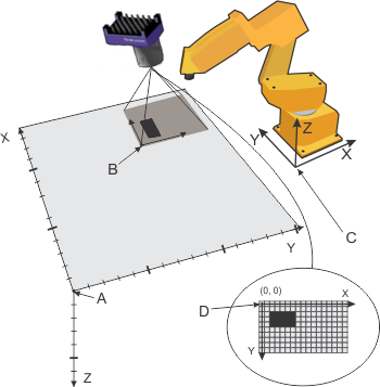
Legend:
|
Marker |
Description |
|
A |
Origin of the absolute coordinate system |
|
B |
Camera field of view |
|
C |
Origin of robot-base coordinate system |
|
D |
Pixel coordinate system |
Calibration by directly mapping the robot coordinate system to the pixel coordinate system
When there is little distortion in your images, it is typically most efficient to link the pixel coordinate system directly to the robot coordinate system. When using this method, you pass new positions to the robot controller directly in the robot coordinate system. You don't need to change the reference frame of the robot controller. In this case, you must know the position of your calibration points in the robot's coordinate system (and in the pixel coordinate system) and calibrate using McalList().

Legend:
|
Marker |
Description |
|
A |
Origin of the absolute coordinate system |
|
B |
Camera field of view |
|
C |
Origin of robot-base coordinate system |
|
D |
Pixel coordinate system |
A minimum of three to seven calibration points are required, depending on the camera calibration mode. Passing more calibration points than the minimum allows the camera calibration to compensate for non-linear robot travel across the work area (the robot moves to a specified point with repeatability, but that point might not be the exact point you wanted it to move to). Use the origin and axes of the robot coordinate system as the origin and axes of the absolute coordinate system. This means that when you specify your calibration points, you do so with respect to the robot coordinate system.
The calibration points do not need to come from a camera calibration grid. You can use any set of known positions, as found on a reference work piece or jig for example. For best accuracy, include locations from the outer limits of the work area. For example, if the object or part is in a box, include the corners of the box as some of the calibration points.
The following are the steps required to perform a camera calibration that directly links the robot and pixel coordinate systems:
In instances where the camera is directly attached to the end point (tool) of the robot arm, you can use the 3D camera calibration mode (M_3D_ROBOTICS) to relate the pixel coordinate system to the robot-base coordinate system without the latter being equivalent to the absolute coordinate system. When using this 3D camera calibration, you can pass positional and rotational data to the robot controller also in the tool coordinate system; however, there must be a rigid link between the camera and the tool.

Legend:
|
Marker |
Description |
|
A |
Origin of the absolute coordinate system. |
|
B |
Camera field of view from which image is captured |
|
C |
Origin of the relative coordinate system |
|
D |
Origin of the tool coordinate system |
|
E |
Origin of the camera coordinate system |
|
F |
Origin of robot-base coordinate system |
|
G |
Pixel coordinate system |
For more information on calibrating using M_3D_ROBOTICS, see the Robotics mode subsection of the Uniform camera calibration and other camera calibration modes section of Chapter 26: Calibrating your camera setup.
Calibration by indirectly mapping the robot and pixel coordinate systems to the world coordinate system
When there is large distortion in your images, it is typically most efficient to map the pixel coordinate system to the robot coordinate system indirectly. When using this method, you pass new positions to the robot controller with respect to some other position, and you must displace the robot's reference frame to this new position.
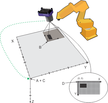
Legend:
|
Marker |
Description |
|
A |
Origin of the absolute coordinate system |
|
B |
Camera field of view |
|
C |
Origin of robot-base coordinate system |
|
D |
Pixel coordinate system |
When using this method, the camera and robot maintain independent mappings of the working area. You specify the location of the origin and axes of the absolute coordinate system both in the pixel coordinate system using MIL and in the robot coordinate system using the robot controller's software that defines its reference frame. This method is quick and easy to implement, but relies on the assumption that MIL and the robot controller return accurate coordinates in the working area.
Use McalList() to calibrate using a list of at least three to seven calibration points, depending on the camera calibration mode. You can also use McalGrid() to calibrate using a grid. You should calibrate using a grid if there are distortions in your image.
The following are the steps suggested to perform a camera calibration that indirectly links the robot and pixel coordinate systems using a grid:
As was previously mentioned, this method is the fastest way to calibrate when large distortions in your image play a factor, because a very large number of calibration points can be included. It is assumed that the robot can very accurately hit the center of any position on the grid based on its row and column position, and therefore this camera calibration method does not require you to collect and record the robot position for all the points.
Communicating with a robot
When communicating with a robot controller, your MIL application should typically wait for the robot controller to request a new position (for example, the location of the next item to pick up), using McomWaitPositionRequest(). When a request is received, your MIL application should grab an image of the item and perform the required analysis to establish the item's position. It should then send the new position to the robot controller using McomSendPosition(). A position for a robot controller consists of six values: X-position, Y-position, Z-position, rotation around X, rotation around Y, and rotation around Z.

For more advanced applications involving multiple object-part types in the camera's field of view, the McomWaitPositionRequest() function can receive from the robot-side application a user-defined number (ObjectSpecifierPtr) that identifies the part or object that the MIL application should locate. Similarly, for applications where multiple occurrences of objects might be present in the field of view, your MIL application should send the robot-side application the user-defined number (ObjectSpecifier) that identifies the object for which it is sending the position.
Orientation conventions
The different rotations about positional axes are represented differently by the robot controllers of various robot manufacturers. The following table shows the notation used for each rotational axis by the robot controller when it displays positional information.
|
Robot type |
Robot controller representation |
||
|
Rotation about the X-axis |
Rotation about the Y-axis |
Rotation about the Z-axis |
|
|
ABB |
The orientation is converted by the robot controller to a quaternion. |
||
|
DENSO |
Roll |
Pitch |
Yaw |
|
Epson |
W |
V |
U |
|
Fanuc |
W |
P |
R |
|
KUKA |
C |
B |
A |
|
Staubli |
Rx |
Ry |
Rz |