McalGrid
- See also

 Availability
 Function map
- Examples
 McalGetCoordinateSystem
- McalInquire

-
The radius of the grid's circles should range between 6 and 10 pixels.
-
The center-to-center distance between the grid's circles should range from 18 to 32 pixels (22 pixels recommended).
-
The minimum distance between the edges of the circles should be 6 pixels.
-
The grid should be large enough to cover the area of the image from which you want real-world results.
-
The grid must be on a single plane although it can be at a slant.
-
The image of the grid should have high contrast.
in the MIL Reference for the minimum update required.
calibrationfromlist.cpp
cameralasercalibration.cpp
cameraonrobotarmcalibration.cpp
examplemanagerfor3d.cpp
m3dmap.cpp
m3dmap.cs
m3dmap.vb
mcal.cpp
mcal.cs
mcal.vb
multiviewannotations.cpp
stereocalibration.cpp
stereorectification.cpp
unwarpmultiviewcylinder.cpp
variouscodereadings.cpp
| Table: | For specifying the row number |
| Table: | For specifying the row spacing |
| Table: | For specifying the type of grid |
| + combination: | For specifying the orientation of the Y-axis |
| + combination: | For increasing the speed of camera calibration |
| MIL_ID CalibrationId, | //in |
| MIL_ID SrcImageBufId, | //in |
| MIL_DOUBLE GridOffsetX, | //in |
| MIL_DOUBLE GridOffsetY, | //in |
| MIL_DOUBLE GridOffsetZ, | //in |
| MIL_INT RowNumber, | //in |
| MIL_INT ColumnNumber, | //in |
| MIL_DOUBLE RowSpacing, | //in |
| MIL_DOUBLE ColumnSpacing, | //in |
| MIL_INT64 Operation, | //in |
| MIL_INT64 GridType | //in |
This function uses an image of a grid of circles or squares and the world description of this grid to establish calibration points, calibrate your camera setup, and create an absolute world coordinate system. If using a circle grid, the center of each circle in the real-world grid is used as a calibration point; if using a chessboard grid, the intersection of four squares/rectangles is used as a calibration point. McalGrid() automatically determines the pixel coordinates of the calibration points in the image using feature extraction algorithms, and calculates the world coordinates of the calibration points using the world description of the grid (number of rows/columns and the space between rows/columns). From these calibration points and the specified calibration mode, McalGrid() establishes a pixel-to-world and world-to-pixel mapping function. The mapping is stored in the specified calibration context.
McalGrid() can also extract calibration points from a special type of chessboard grid which contains a fiducial; this is referred to as a fiducial grid. The fiducial supported in a fiducial grid is a Data Matrix code that encodes the world description of the grid itself. This information includes the grid spacing, the units in which the spacing is measured, the position of the grid's reference calibration point, and the grid's orientation.
MIL is distributed with five different camera calibration grids that you can print and use: ChessboardCalibrationGrid_15x16_Letter.pdf, ChessboardCalibrationGrid_18x22_Letter.pdf, CircleCalibrationGrid_15x16_Letter.pdf, CircleCalibrationGrid_18x22_Letter.pdf, and FiducialCalibrationGrid_Letter.pdf. These files are located in the Matrox Imaging\Images directory. Each file includes the world description of the grid. For guidelines when printing the grid, see the Printing the grid subsection of the Generating a grid for calibration section of Chapter 26: Calibrating your camera setup.
After calling McalGrid(), you can inquire about the success of the camera calibration using McalInquire() with M_CALIBRATION_STATUS. You can inquire about the accuracy of the mapping function (camera calibration error) using McalInquire() with M_AVERAGE_PIXEL_ERROR, M_MAXIMUM_PIXEL_ERROR, M_AVERAGE_WORLD_ERROR, or M_MAXIMUM_WORLD_ERROR. In addition, you can visualize the calibration points that were used, using McalDraw() with M_DRAW_IMAGE_POINTS; this visualization can be especially effective when overlaid on the image of the original grid. It is important that the extracted calibration points are directly in the middle of each circle, for a circle grid, and at the intersection of the grid squares/rectangles, for a chessboard grid. Any extra points, missing points, or imprecisely positioned points will result in calibration inaccuracy. For more information, see the Inquiring about your camera calibration section of Chapter 26: Calibrating your camera setup.
In the default calibration mode, M_LINEAR_INTERPOLATION mode, a mapping function is created so that comparing transformed coordinates (either pixel-to-world or world-to-pixel) of the calibration points results in virtually no measured calibration error. This produces increased calibration accuracy for areas of the image inside the grid and reduced accuracy for areas outside the grid. For all other calibration modes, the mapping function applies the calibration error equally to all areas in the image, regardless of where the grid was in the image. If there are any problems with the mapping function, the calibration error is averaged out over the entire image.
For 3D-based camera calibration modes (M_TSAI_BASED or M_3D_ROBOTICS), it is possible to use a grid that is not in the XY-plane (Z=0) of the absolute coordinate system. This allows you to account for two XY-planes in the working area of the camera or even for the thickness of the calibration grid itself. For both cases, you can use the GridOffsetZ parameter to specify the height or thickness of the grid being used.
When working in M_3D_ROBOTICS camera calibration mode, you must first call this function with M_ACCUMULATE at least three times to accumulate data with different images and orientations. Calling this function with M_ACCUMULATE more than 3 times improves the accuracy of the camera calibration. Before each data accumulation call, you must change the position and orientation of the tool holding the camera with respect to the robot base. More specifically, you must rotate the tool along at least two non-parallel axes. You must also use McalSetCoordinateSystem() to set the position of the tool coordinate system with respect to the robot base coordinate system before each of these calls. When you are done accumulating data, you must call this function with M_FULL_CALIBRATION and no image to perform the full camera calibration. Once you perform a full camera calibration, you can no longer accumulate camera calibration poses.
For 3D-based camera calibration modes, McalGrid() performs two types of calculations. It calculates the camera's internal attributes, and it calculates the orientation and distance between the camera and camera calibration plane. Initially, the latter is used to set the camera coordinate system. If you move the camera or the grid (not both), you can have McalGrid() recalculate only the orientation and distance between them. In this case, depending on what you moved, you can specify that McalGrid() displace either the camera coordinate system or the relative coordinate system, using M_DISPLACE_CAMERA_COORD or M_DISPLACE_RELATIVE_COORD, respectively. When using M_DISPLACE_RELATIVE_COORD, the camera calibration plane is considered to be the XY-plane of the relative coordinate system, regardless of how McalControl() with M_CALIBRATION_PLANE is set.
Note that the internal attributes calculated for the camera are not those of the physical camera, but those of the ideal pinhole-camera used to model the physical camera.
Also, for 3D-based camera calibration modes, a successful call to McalGrid() with M_FULL_CALIBRATION creates a rigid link between the camera coordinate system and the tool coordinate system. This link ensures that moving either the tool or the camera coordinate system will affect both. This link can be broken using McalControl() with M_LINK_TOOL_AND_CAMERA.
Note that for an M_3D_ROBOTICS calibration context, which requires multiple calls to McalGrid(), you can inquire about any particular call using McalInquireSingle().
Depending on the type of calibration grid and the orientation of the camera and grid in your setup, you might have to specify a hint pixel to indicate the grid's reference calibration point, used to determine the origin of the absolute coordinate system. You can do this using McalControl() set to M_GRID_HINT_PIXEL_X and M_GRID_HINT_PIXEL_Y. Note that the default position of the reference calibration point for complete grids (grids that are unobstructed and show all specified rows and columns) is the calibration point in the corner of the grid closest to the top-left corner of the image. For chessboard grids that are partially obscured and for all fiducial grids, the default reference calibration point is the calibration point closest to the center of the image.
You can limit results to a region of interest (ROI) of an image buffer using MbufSetRegion(). The ROI must be defined in raster format (M_RASTER or M_VECTOR_AND_RASTER). An error is generated if the ROI is only in vector format (M_VECTOR).
For more information on performing camera calibration using a chessboard or circle grid, see the Calibrating using calibration points from a grid section of Chapter 26: Calibrating your camera setup. For information on camera calibration using a fiducial grid, see the Calibrating using a fiducial grid section of Chapter 26: Calibrating your camera setup.
Specifies the identifier of the image buffer containing the grid. It must be an 8- or 16-bit unsigned buffer, with 1 or 3 bands.
This image buffer can have a region of interest (ROI) associated with it (set using MbufSetRegion()). The ROI must be defined in raster format (M_RASTER or M_VECTOR_AND_RASTER). An error is generated if the ROI is only in vector format (M_VECTOR).
Note that the source image used for camera calibration is automatically calibrated after a successful call to McalGrid() with M_FULL_CALIBRATION.
When performing a M_FULL_CALIBRATION operation in M_3D_ROBOTICS camera calibration mode, set this parameter to M_NULL.
Specifies the X-coordinate of the grid's reference calibration point, in the real world. Specify its X-coordinate in the world coordinate system specified using McalControl() with M_CALIBRATION_PLANE. Typically, set this value to 0.
When performing a M_FULL_CALIBRATION operation in M_3D_ROBOTICS camera calibration mode, set this parameter to M_NULL.
Specifies the Y-coordinate of the grid's reference calibration point, in the real world. Specify its Y-coordinate in the world coordinate system specified using McalControl() with M_CALIBRATION_PLANE. Typically, set this value to 0.
When performing a M_FULL_CALIBRATION operation in M_3D_ROBOTICS camera calibration mode, set this parameter to M_NULL.
Specifies the Z-coordinate of the grid's reference calibration point, in the real world. Specify its Z-coordinate in the world coordinate system specified using McalControl() with M_CALIBRATION_PLANE. Typically, set this value to 0.
For 2D-based camera calibration modes, or when performing a M_FULL_CALIBRATION operation in M_3D_ROBOTICS camera calibration mode, set this parameter to M_NULL.
Specifies the number of rows in the camera calibration grid.
|
For specifying the row number |
|||||||||||||||||||||||||||||||||||||||
| Description | |||||||||||||||||||||||||||||||||||||||
|
Specifies that you are performing a M_FULL_CALIBRATION operation in M_3D_ROBOTICS camera calibration mode. |
|||||||||||||||||||||||||||||||||||||||
|
Specifies that you are calibrating using a partial chessboard grid. This can be set if and only if McalControl() with M_GRID_PARTIAL is set to M_ENABLE. (summarize)Specifies that you are calibrating using a partial chessboard grid. (more details...) |
|||||||||||||||||||||||||||||||||||||||
|
Specifies the total number of rows in the real-world grid. Generally, camera calibration accuracy increases with the number of rows. The minimum number of rows is 2 when GridType is set to M_CIRCLE_GRID and 3 when set to M_CHESSBOARD_GRID. For M_TSAI_BASED and M_3D_ROBOTICS camera calibration modes, you must provide a grid that contains at least 6 grid points, even though the minimum number of rows and the minimum number of columns are both 2. Note that in the case of a rotated image of a rectangular camera calibration grid, you must specify the number of rows of the real-world grid and not the number of rows as there appears to be in the rotated image of the grid. (summarize)Specifies the total number of rows in the real-world grid. (more details...) |
|||||||||||||||||||||||||||||||||||||||
Specifies the number of columns in the camera calibration grid.
|
For specifying the column number |
|||||||||||||||||||||||||||||||||||||||
| Description | |||||||||||||||||||||||||||||||||||||||
|
Specifies that you are performing a M_FULL_CALIBRATION operation in M_3D_ROBOTICS camera calibration mode. |
|||||||||||||||||||||||||||||||||||||||
|
Specifies that you are calibrating using a partial chessboard grid. This can be set if and only if McalControl() with M_GRID_PARTIAL is set to M_ENABLE. (summarize)Specifies that you are calibrating using a partial chessboard grid. (more details...) |
|||||||||||||||||||||||||||||||||||||||
|
Specifies the total number of columns in the real-world grid. Generally, camera calibration accuracy increases with the number of columns. The minimum number of columns is 2 when GridType is set to M_CIRCLE_GRID and 3 when set to M_CHESSBOARD_GRID. For M_TSAI_BASED and M_3D_ROBOTICS camera calibration modes, you must provide a grid that contains at least 6 grid points, even though the minimum number of rows and the minimum number of columns are both 2. Note that in the case of a rotated image of a rectangular camera calibration grid, you must specify the number of columns of the real-world grid and not the number of rows as there appears to be in the rotated image of the grid. (summarize)Specifies the total number of columns in the real-world grid. (more details...) |
|||||||||||||||||||||||||||||||||||||||
Specifies the number of world units between rows.
|
For specifying the row spacing |
|||||||||||||||||||||||||||||||||||||||
| Description | |||||||||||||||||||||||||||||||||||||||
|
Specifies to not use row spacing. You must set this value when performing a M_FULL_CALIBRATION operation in M_3D_ROBOTICS camera calibration mode. (summarize)Specifies to not use row spacing. (more details...) |
|||||||||||||||||||||||||||||||||||||||
|
Specifies to set the row spacing according to the data in the chessboard grid fiducial. |
|||||||||||||||||||||||||||||||||||||||
|
Specifies the row spacing, in world units. |
|||||||||||||||||||||||||||||||||||||||
Specifies the number of world units between columns.
|
For specifying the column spacing |
|||||||||||||||||||||||||||||||||||||||
| Description | |||||||||||||||||||||||||||||||||||||||
|
Specifies to not use column spacing. You must set this value when performing a M_FULL_CALIBRATION operation in M_3D_ROBOTICS camera calibration mode. (summarize)Specifies to not use column spacing. (more details...) |
|||||||||||||||||||||||||||||||||||||||
|
Specifies to set the column spacing according to the data in the chessboard grid fiducial. |
|||||||||||||||||||||||||||||||||||||||
|
Specifies the column spacing, in world units. |
|||||||||||||||||||||||||||||||||||||||
Specifies the camera calibration operation to perform. This parameter must be set to one of the following values:
|
For specifying the camera calibration
operation |
|||||||||||||||||||||||||||||||||||||||
| Description | |||||||||||||||||||||||||||||||||||||||
|
Same as M_FULL_CALIBRATION. |
|||||||||||||||||||||||||||||||||||||||
|
Calculates only the position of the calibration points and stores them in the camera calibration context. At least three calls to McalGrid() should be made with this operation before performing the full camera calibration with M_FULL_CALIBRATION. This operation is only supported for M_3D_ROBOTICS camera calibration. (summarize)Calculates only the position of the calibration points and stores them in the camera calibration context. (more details...) |
|||||||||||||||||||||||||||||||||||||||
|
Calculates only the position and orientation between the camera and the camera calibration plane, and displaces the camera coordinate system accordingly. Note that besides the camera coordinate system, this also displaces the tool coordinate system (if still linked with M_LINK_TOOL_AND_CAMERA); no other coordinate system is affected. This camera calibration operation is only supported for 3D-based camera calibration contexts that are fully calibrated with M_FULL_CALIBRATION. If the camera is moved to a new position but its internal attributes are already known by a previous full camera calibration, you can use this operation to allow for a faster camera calibration. (summarize)Calculates only the position and orientation between the camera and the camera calibration plane, and displaces the camera coordinate system accordingly. (more details...) |
|||||||||||||||||||||||||||||||||||||||
|
Calculates only the position and orientation between the camera and the camera calibration plane, and displaces the relative coordinate system accordingly. This camera calibration operation is only supported for 3D-based camera calibration contexts that are fully calibrated with M_FULL_CALIBRATION. You can use this operation to move the relative coordinate system only and remain calibrated. This operation keeps the camera fixed with respect to the absolute coordinate system, and its intrinsic attributes unmodified. You can then obtain the position and orientation of the relative coordinate system with respect to any other coordinate system using McalGetCoordinateSystem(), and calculate the unknown position of an object in space. When using this operation, the camera calibration plane is considered to be the relative coordinate system regardless of the M_CALIBRATION_PLANE setting. (summarize)Calculates only the position and orientation between the camera and the camera calibration plane, and displaces the relative coordinate system accordingly. (more details...) |
|||||||||||||||||||||||||||||||||||||||
|
Performs a full camera calibration. For 3D-based camera calibration contexts, this operation calculates the camera's internal attributes and the difference in position and orientation between the camera and the camera calibration plane. It then sets the camera coordinate system accordingly. When working in M_TSAI_BASED camera calibration mode, the camera's optical axis should be at least 30 degrees away from the axis perpendicular to the camera calibration plane (also known as, angle of incidence). Otherwise, the camera calibration might fail. (summarize)Performs a full camera calibration. (more details...) |
|||||||||||||||||||||||||||||||||||||||
Specifies the type of grid used. This parameter must be set to one of the following values:
|
For specifying the type of grid |
|||||||||||||||||||||||||||||||||||||||
| Description | |||||||||||||||||||||||||||||||||||||||
|
Same as M_CIRCLE_GRID. |
|||||||||||||||||||||||||||||||||||||||
|
Specifies a chessboard grid. The number of rows and columns represents the number of corners horizontally and vertically. A corner is the intersection of 4 cells, meaning that the corners on the perimeter do not count. Note that, for a chessboard grid type, the number of rows and the number of columns must be at least 3. The following is an example of a valid 4x4 chessboard grid. 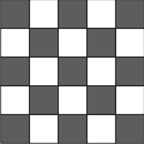
Note that when calibrating using a chessboard grid, the entire grid does not have to be present in the camera calibration image. In this case, you must call McalControl() with M_GRID_PARTIAL set to M_ENABLE. (summarize)Specifies a chessboard grid. (more details...) |
|||||||||||||||||||||||||||||||||||||||
|
Specifies a grid of circles. Note that, for a grid of circles, the number of rows and the numbers of columns must be at least 2. To create an accurate (subpixel) mapping, the image of the grid should meet the following guidelines (at the working resolution): Note that circle grids must be complete grids in which all circles are present in a rectangular grid. (summarize)Specifies a grid of circles. (more details...) |
|||||||||||||||||||||||||||||||||||||||
You can add one of the following values to the above-mentioned values to set the orientation of the Y-axis.
These combination values are not supported if using M_UNIFORM_TRANSFORMATION camera calibration mode.
|
For specifying the orientation of the Y-axis
INQ
|
|||||||||||||||||||||||||||||||||||||||
| Description | |||||||||||||||||||||||||||||||||||||||
|
Orients the positive Y-axis 90° clockwise from the X-axis. Typically, for a complete grid that has its reference calibration point at the top-left of the grid, the orientation of the Y-axis is along the first column of circles in a grid of circles or along the leftmost vertical line of intersection points in a chessboard grid. The axis is oriented from the top to the bottom. This is the default value. (summarize)Orients the positive Y-axis 90° clockwise from the X-axis. (more details...) |
|||||||||||||||||||||||||||||||||||||||
|
Orients the positive Y-axis 90° counter-clockwise from the X-axis. Typically, for a complete grid that has its reference calibration point at the top-left of the grid, the orientation of the Y-axis is along the first column of circles in a grid of circles, or along the leftmost vertical line of intersection points in a chessboard grid. The axis is oriented from the bottom to the top. (summarize)Orients the positive Y-axis 90° counter-clockwise from the X-axis. (more details...) |
|||||||||||||||||||||||||||||||||||||||
You can add the following value to the above-mentioned value to set the speed of camera calibration.
|
For increasing the speed of camera
calibration
|
|||||||||||||||||||||||||||||||||||||||
| Description | |||||||||||||||||||||||||||||||||||||||
|
Speeds up the time it takes to perform the camera calibration by using a faster camera calibration algorithm. Note that using a faster camera calibration algorithm can decrease the robustness and accuracy of the camera calibration. When using M_FAST, memory consumption is reduced. (summarize)Speeds up the time it takes to perform the camera calibration by using a faster camera calibration algorithm. (more details...) |
|||||||||||||||||||||||||||||||||||||||
| Header | Include mil.h. |
| Library | Use mil.lib; milcal.lib. |
| DLL | Requires mil.dll; milcal.dll. |