Calibrating using calibration points from a grid
- See also

 Availability
 Previous
- Next

-
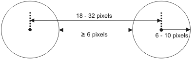
The radius of the grid's circles should range between 6 and 10 pixels.
-
The center-to-center distance between the grid's circles should range from 18 to 32 pixels (22 pixels recommended).
-
The minimum distance between the edges of the circles should be 6 pixels.
-
The grid should be large enough to cover the area of the image from which you want real-world results (the working area).
-
The grid image should have high contrast.
-
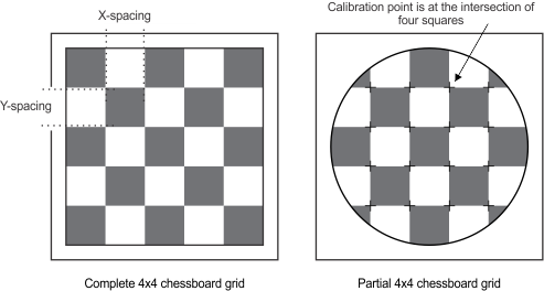
The squares/rectangles should each be at least 12 X 12 pixels. In the case of rectangles or squares with perspective distortion, the smallest dimension should be at least 12 pixels.
-
The physical grid and the grid image should be clear of specks, dirt, and noise. This can be achieved by cleaning the physical grid and/or preprocessing the image, as much as possible.
-
The grid should have little to no saturation.
-
The grid image should have high contrast.
-
You can calibrate your camera using a partial chessboard grid, but not a partial circle grid. Circle grids must be complete.
-
You must explicitly enable camera calibration with partial grids, using McalControl() with M_GRID_PARTIAL, prior to calling McalGrid().
-
For a partial grid, the grid's default reference calibration point (used to determine the origin of the absolute coordinate system) is the calibration point closest to the center of the image. You can specify a non-default reference calibration point by specifying a grid hint pixel, using McalControl() with M_GRID_HINT_PIXEL_X and M_GRID_HINT_PIXEL_Y. The grid's reference calibration point will be the calibration point closest to the grid hint pixel.
-
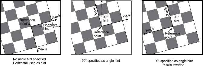
The grid's orientation is determined by the two grid lines intersecting at the reference calibration point. The X- and Y-axes are always aligned with the grid lines. By default, the X-axis of the absolute coordinate system is the grid line intersecting the reference calibration point and closest to the image's X-axis, with the positive X-axis pointing right. To specify the other grid line and/or direction for the positive X-axis, you must specify McalControl() with M_GRID_HINT_ANGLE_X. When you specify a hint angle, the positive X-axis will be the grid line intersecting the reference calibration point and closest in angle to the hint angle. The Y-axis is 90° clockwise from the X-axis, unless it is inverted using McalGrid() with M_CHESSBOARD_GRID + M_Y_AXIS_COUNTER_CLOCKWISE.
-
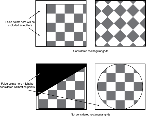
You can specify how to handle potential invalid calibration points, using McalControl() with M_GRID_SHAPE. Choosing between setting M_GRID_SHAPE to M_RECTANGLE or M_ANY helps McalGrid() determine where the edge of the chessboard grid is. With the knowledge of the edge of the grid, it becomes easier to determine if a calibration point found near the edge is valid (from the grid) or invalid (from noise).
By default, M_GRID_SHAPE is set to M_RECTANGLE. This assumes that the edges of the grid can be found. Once a grid edge is found, any potential calibration point found beyond the grid edge can be ignored. You can keep the default value (M_RECTANGLE) even when the grid is partially occluded by the image border, as long as the shape of the visible edges of the grid are rectangular (straight edges connected in 90° angles).
Set M_GRID_SHAPE to M_ANY when the physical chessboard grid is not rectangular, for instance a circular or triangular grid that fits inside some enclosure, or when the grid is occluded by some object. In this case, all potential calibration points will be included in the camera calibration, possibly including false calibration points near the edge of the grid caused by noise. This has the effect of potentially reducing the quality of the camera calibration.
To calibrate your camera setup, you can specify points in the image and map them to real-world coordinates. These are known as calibration points. You can have MIL automatically determine the calibration points from an image of a user-defined grid and the world description of this grid. To do so, use McalGrid(). The world description includes the number of rows and columns, as well as the point-to-point distance between these rows and columns, in real-world units. The number of rows and columns in your grid are used to specify the number of calibration points that McalGrid() extracts. Real-world calibration points on the grid, with known spacing between points, are mapped to pixels in the grid's image to establish the image calibration points. The origin and axes of the absolute coordinate system are determined based on the position of the calibration points.
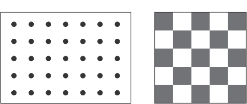
McalGrid() can use a grid of circles (M_CIRCLE_GRID) or a chessboard grid (that is, grid of squares/rectangles - M_CHESSBOARD_GRID).
McalGrid() can also use fiducial grid, which is a chessboard grid with a Data Matrix code that encodes information about the grid itself. Fiducial grids are especially useful when calibrating multiple camera setups to use the same absolute coordinate system. For information on fiducial grids, see the Calibrating using a fiducial grid section later in this chapter.
MIL is distributed with five different camera calibration grids that you can print and use: ChessboardCalibrationGrid_15x16_Letter.pdf, ChessboardCalibrationGrid_18x22_Letter.pdf, CircleCalibrationGrid_15x16_Letter.pdf, CircleCalibrationGrid_18x22_Letter.pdf, and FiducialCalibrationGrid_Letter.pdf. These files are located in the Matrox Imaging\Images directory. Each file includes the world description of the grid.
For information on generating a chessboard grid with your own specifications, see the Generating a grid for calibration section later in this chapter.
Requirements for the image of the grid
To create an accurate (subpixel) pixel-to-world mapping, your grid image must have a certain minimum number of calibration points and it should meet a set of guidelines at the working resolution, depending on the type of grid.
Requirements for the image of a circle grid
In a circle grid, the center of each circle in the real-world grid is used as a calibration point. When using a circle grid, to perform a full camera calibration with a 2D camera calibration context, the grid image must have at least 2x2 calibration points; for a 3D camera calibration context, the grid image must have at least 2x3 or 3x2 calibration points.
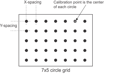
The image of the circle grid should meet the following guidelines:
Requirements for the image of a chessboard grid
In a chessboard grid, the intersection of four squares/rectangles is used as a calibration point. When using a chessboard grid to perform a full camera calibration with a 2D or a 3D camera calibration context, the grid image must have at least 3x3 calibration points. Note that for the chessboard grid image to have 3x3 calibration points, it must have at least 4 columns and 4 rows.
The image of the chessboard grid can be either the complete grid with 4 clearly defined border edges or some part of the grid, as in the image below. If you are using an image with a partial chessboard grid to calibrate your camera setup, you must call McalControl() with M_GRID_PARTIAL set to M_ENABLE.
By default, camera calibration using partial grids is disabled (M_GRID_PARTIAL set to M_DISABLE). In this case, the complete grid should be visible, including the outermost boundary squares/rectangles. Any occlusion of the grid can result in problems. The number of rows and columns specified when calling McalGrid() must equal the number of rows and columns found in the image of the grid.
When partial grids are enabled (M_GRID_PARTIAL set to M_ENABLE), the chessboard grid in your image can be occluded, either by the edge of the image or by an object within the image. For partial grids, you do not explicitly specify the number of rows and columns when calling McalGrid(), so the grid can have any number of rows and columns. For more information on partial grids, see the Calibrating with a partial chessboard grid subsection of this section. Note that only chessboards grids can be partial. Circle grids must always be complete.
For both complete and partial grids, the image of the chessboard grid should meet the following guidelines:
Defining the absolute coordinate system
Calibration defines the absolute coordinate system. McalGrid() takes a grid, finds the grid's reference calibration point, which typically becomes the origin of the absolute coordinate system, and finds the grid lines, two of which become the axes of the absolute coordinate system.
Note that while McalGrid() typically defines the absolute coordinate system directly, it can be used to define the relative coordinate system directly and the absolute coordinate system indirectly. For more information on when and how you should define the relative coordinate system directly, see the Defining the relative coordinate system directly subsection of this section.
Determining the grid's reference calibration point
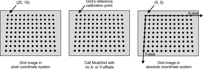
For circle grids and complete chessboard grids, the calibration point closest to the top-left corner of the grid image is the grid's reference calibration point. The reference calibration point, along with the offset parameters of McalGrid(), determine the origin (0, 0) of the absolute coordinate system. The X- and Y-axes of the absolute coordinate system are aligned with the top-most row and left-most column of the grid, respectively. Typically, the offset parameters are set to 0, which makes the grid's reference calibration point the origin of the absolute coordinate system.
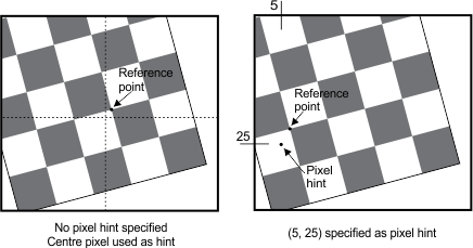
If the grid appears rotated in the image such that the grid's reference calibration point is not in the top-left corner of the image, you must specify where the grid's reference calibration point is in the image. The grid can appear rotated in the image for two different reasons: because the physical grid is rotated or because the camera is rotated. Regardless of the reason, the solution is the same: specify a hint pixel.
Specify a hint pixel that is close to the grid's reference calibration point in the rotated image. To do so, use McalControl() with M_GRID_HINT_PIXEL_X and M_GRID_HINT_PIXEL_Y before calling McalGrid(). For instance in the following image, the image of the grid appears rotated 90º, so the grid's reference calibration point is roughly at the pixel coordinates (225, 25). In this case, you would set your hint pixel to any pixel close to (225, 25), and then call McalGrid(). There are at most 4 corners to the grid (or 2 valid corners, given a rectangular grid with a known number of rows and columns), so the rough estimate of the pixel coordinates of the reference calibration point do not have to be precise. The closest valid corner to the specified coordinates will be used as the grid's reference calibration point.
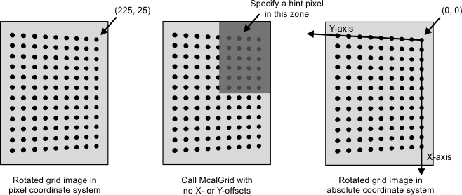
Note that in this example, the real-world grid has 9 horizontal rows and 12 vertical columns. However, the grid appears rotated in the image; so, it seems to have 12 horizontal rows and 9 vertical columns. It is important to specify the real-world values of 9 rows and 12 columns when calling McalGrid(), regardless of how the grid looks in the rotated image. McalGrid() looks for the closest valid corner, given the hint pixel and the number of rows and columns. Also note that, in this example, if a hint pixel is specified near to the opposite corner, the absolute coordinate system's origin would be placed there, which is the only other possible valid corner for a non-square grid.
Inverting the rows and columns will not cause an error, but might change the grid's reference calibration point and the orientation of the axes.
Using the X- and Y-offsets
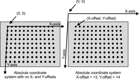
Once McalGrid() has determined the grid's reference calibration point and orientation, it applies the specified X- and Y-offsets to determine the origin of the absolute coordinate system. Whatever values you specify for the X- and Y-offsets will be the coordinates of the grid's reference calibration point in the absolute coordinate system. Typically, you specify 0 for the X- and Y-offsets, which means that the grid's reference calibration point is at the origin of the absolute coordinate system. You can, however, specify any values for the offsets; the offsets are specified in real-world units.
Note that the origin of the absolute coordinate system does not have to be within the field-of-view.
Note that for 3D calibration modes, you can also offset along the Z-axis. If your grid is parallel to the surface that you want to use to define the absolute coordinate system, but not at the same height, you should compensate for the height difference using the Z-offset parameter when calling McalGrid(). This can be used even for a small height differential caused by the thickness of the grid itself. For more information, see the Moving the relative coordinate system to account for height section of Chapter 31: 3D analysis using planar views of an object.
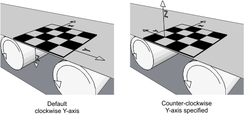
Inverting the orientation of the Y-axis
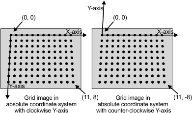
By default, the Camera Calibration module assumes the Y-axis is oriented 90° clockwise with respect to the positive X-axis. You can have the positive Y-axis oriented 90° counter-clockwise with respect to the positive X-axis using McalGrid() with M_CIRCLE_GRID or M_CHESSBOARD_GRID and the combination constant M_Y_AXIS_COUNTER_CLOCKWISE.
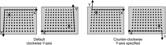
Note that the orientation of the absolute coordinate system in the image of the grid is affected by the location of the hint pixel specified using McalControl() with M_GRID_HINT_PIXEL_X and M_GRID_HINT_PIXEL_Y. In the following images, the bold X in the grid is the hint pixel.
Note that in the case of 3D calibrations, there is also the Z-axis to consider. By default, the Z-axis is pointing downward, typically away from the camera. When the Y-axis is inverted using M_Y_AXIS_COUNTER_CLOCKWISE, the Z-axis also inverts, so that the 3D coordinate systems always remains right-handed. When inverted, the Z-axis points upward, typically toward the camera, as illustrated in the image below.
Calibrating with a partial chessboard grid
In some circumstances, such as when the camera placement necessitates that the grid be partially occluded, you can calibrate your camera with a partial grid. In this case, there are special considerations.
Defining the relative coordinate system directly
In most circumstances, calibrating your camera will define the absolute coordinate system. The grid's reference calibration point, the axes directions, and the specified X- and Y-offsets, define the origin and orientation of the absolute coordinate system. This is the default behavior. Note that when you define the absolute coordinate system, you indirectly define your relative coordinate system to be, by default, at the same place as the absolute.
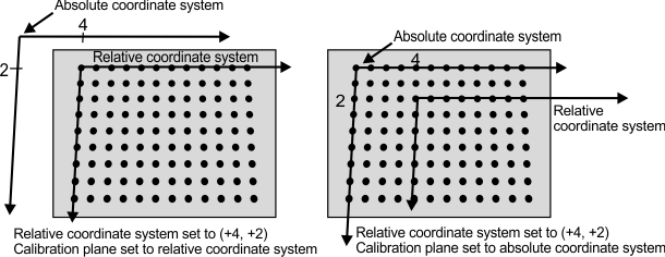
You can, however, define the relative coordinate system directly and the absolute coordinate system indirectly, by calling McalControl() with M_CALIBRATION_PLANE set to M_RELATIVE_COORDINATE_SYSTEM. This can be useful when calibrating a M_TSAI_BASED camera context.
By default, the relative and absolute coordinate system overlap when they are first created using McalGrid(), so defining the absolute coordinate system directly or the relative coordinate system directly is identical. However, you can specify a position and orientation for the relative coordinate system, with respect to the absolute coordinate system, before either are officially created. If the relative coordinate system is offset from the absolute coordinate system before calling McalGrid(), specifying whether the camera calibration grid represents the relative or the absolute coordinate system with M_CALIBRATION_PLANE make a difference.
In the image below, before calling McalGrid(), the relative coordinate system was specified (using McalRelativeOrigin() or McalSetCoordinateSystem()) to be translated away from the absolute coordinate system by 4 units in the X-axis, 2 units in the Y-axis, and 0 in the Z-axis. The image on the left shows the placement of the two coordinate systems when M_CALIBRATION_PLANE is set to M_RELATIVE_COORDINATE_SYSTEM. The image on the right shows the placement when M_CALIBRATION_PLANE is set to M_ABSOLUTE_COORDINATE_SYSTEM. Note that in both images, the relative coordinate system has the same position relative the absolute coordinate system.
Calibrating a Tsai based camera calibration context when the camera is directly overhead
When calibrating a M_TSAI_BASED camera calibration context, typically, your camera must be positioned so that it has perspective distortion. In the case of a camera setup with a camera directly overhead the working area, there is no natural perspective distortion, presenting a challenge to camera calibration. This challenge can be addressed using McalControl() with M_CALIBRATION_PLANE.
Lift one side of the grid to a known angle, for instance by placing the grid on an accurately manufactured wedge. Before grabbing the image of the grid, set the position of the relative coordinate system such that the relative coordinate system is offset from the absolute coordinate system (the working area) at the precise angle of the wedge the grid is resting on (using McalSetCoordinateSystem()). Now, change the calibration plane to the relative coordinate system (using McalControl() with M_CALIBRATION_PLANE set to M_RELATIVE_COORDINATE_SYSTEM), grab an image of the grid on the wedge, and calibrate the camera (using McalGrid()). The relative coordinate system will be at the angle of the grid on the wedge and the absolute coordinate system will be the working area. You can then realign the relative coordinate system so that it is on or parallel to the same surface as the absolute coordinate system.