Peak intensity detection and depth maps
- See also

 Availability
 Previous
- Next

-
Allocate an image buffer, using MbufAlloc2d(). This will be used for the depth map or intensity map. The width and height of the image buffer have constraints.
The image buffer must have a width greater than or equal to the number of lanes (laser line image width or height, depending on whether the image has a horizontal or vertical laser line, respectively). This is because MimDraw() draws the results obtained for each lane in a laser line image into a single row of the depth map or intensity map image buffer, regardless of the orientation.
The image buffer must have a height greater than or equal to the expected number of laser line images of the object that you will grab. Results from each grabbed image will be drawn in a new row of the depth map or intensity map image buffer.
-
Iterate through the following steps for each image in the series of laser line images.
-
Grab a new laser line image.
-
Call MimLocatePeak1d() on the laser line image.
-
Call MimDraw() with the locate peak 1D result buffer and the allocated depth map or intensity map image buffer, incrementing the row of the depth map and/or intensity map image buffer in which to write.
In addition, pass M_DRAW_DEPTH_MAP_ROW or M_DRAW_INTENSITY_MAP_ROW, depending on whether you want to draw the depth map or intensity map, respectively. To draw both, you must call MimDraw() twice in each loop.
-
It is sometimes useful to find the position of the highest intensity in every lane (row or column) of an image. MimLocatePeak1d() performs very fast and efficient peak intensity detection on each lane of pixels in a source image. The peak is the 1D neighborhood of pixels that have the highest intensity in the lane. Once the function finds the peak neighborhood of the lane, it records the sub-pixel position of the peak intensity, and the average intensity around that sub-pixel position.
You can, for example, create a structured light application using MimLocatePeak1d() with images from a laser line profiling setup, to establish depth and surface information for an object in a scene. A basic laser line profiling setup consists of: a device projecting a sheet of light (usually a laser diode), a camera, and a mechanism to move the object under the laser plane. The camera is used to grab an image of the intersection of the laser plane with the object. From the way that the laser line deforms when striking the object's surfaces, depth and surface information can be established for that slice of the object.
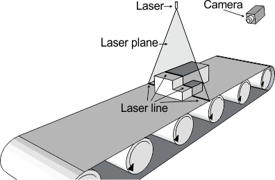
By grabbing a sequence of images as the object moves underneath the laser plane, and then processing the images with MimLocatePeak1d() and MimDraw(), you can generate an uncorrected depth map of the exposed topography of the object. An uncorrected depth map is an image where the gray value of a pixel represents its depth in the world, although the depth is not its actual world depth and its shape is not corrected for the angle of the camera. If your application requires accurate depth or shape information, see the Generating fully corrected depth and intensity maps section of Chapter 32: 3D image processing for more information on how to create a depth map.
Setting up peak intensity detection
MimLocatePeak1d() requires its own context (MimAlloc() with M_LOCATE_PEAK_1D_CONTEXT) and its own result buffer (MimAllocResult() with M_LOCATE_PEAK_1D_RESULT), as well as a source image from which to locate the peak intensities. To understand how to set the function to optimally find the peak in each lane, you should understand how the function works.
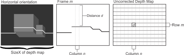
The function scans each lane and records each lane's peak position and intensity. The peak's position is the sub-pixel distance from the origin of the lane to the sub-pixel point with the highest intensity in the peak. The peak's intensity is the average gray value of the few pixels around the sub-pixel position of the peak.

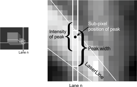
Peaks are a 1D neighborhood of pixels, despite having a sub-pixel position. In a laser line image, the peak is typically the width of the laser line, in pixels. Peaks have a configurable range of acceptable widths; you can specify the average width of the laser line (nominal width) and how much that average width can vary (delta width). The range is: nominal-delta <= peak width <= nominal+delta.
When looking for a peak in a lane, MimLocatePeak1d() focuses on the contrast between the intensity of the pixels of the local background and the intensity of the pixels of the suspected peak; you can specify the minimum contrast. For example, if the local background intensity is 80, and you want the minimum intensity in your peak neighborhood to be 230, you would specify the minimum contrast to be 150.
Once a peak is suspected, the number of continuous pixels that fulfill the contrast condition are counted. Provided the total number of pixels that fulfill the contrast condition is within the range of allowable peak widths, the peak is recorded. The position of the peak is the sub-pixel position of the highest intensity within the peak width. The intensity of the peak is the average intensity of a few pixels around the peak position; you can specify how many pixels are used to calculate the peak intensity using MimControl() with M_PEAK_INTENSITY_RANGE. Note that the peak position is not always at the center of the neighborhood, as can be seen in the following zoomed image. Also note that the peak intensity is not exclusively determined by the pixels in the peak width and can include some background pixels.
Typically, you set the values for the nominal width, the delta width, and the minimum contrast when you call MimLocatePeak1d(). However, you can set the parameters to M_DEFAULT and set the values for the nominal width, the delta width, and the minimum contrast using MimControl() with M_PEAK_WIDTH_NOMINAL, M_PEAK_WIDTH_DELTA, and M_MINIMUM_CONTRAST, respectively.
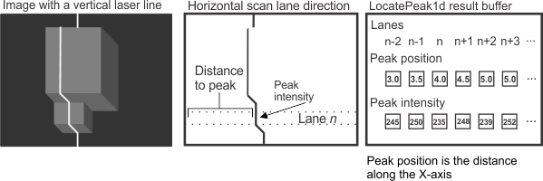
Note that by default, MimLocatePeak1d() scans vertical lanes (columns) in the source image, storing the peak position as the Y-coordinate; this is useful for detecting horizontal laser lines. However, you can specify that MimLocatePeak1d() scans horizontal lanes (rows), using MimControl() with M_SCAN_LANE_DIRECTION set to M_HORIZONTAL, for example, to look for a vertical laser line. In this case, the peak position stored in the result buffer will be the X-coordinate, as shown in the image below:
For optimal performance, preprocess the result buffer by calling MimLocatePeak1d() with M_PREPROCESS. You can choose to preprocess with or without an image. When preprocessing with an image, specify a typical image in the series of images that you will process using MimLocatePeak1d(). The preprocessed image's size and bit-depth are stored. When preprocessing without an image, you must specify the number of scan lanes in each of the images in the series. When preprocessing without an image, it is assumed that all images are 8-bit unsigned.
If the preprocess operation is not done explicitly (using M_PREPROCESS) or correctly, MimLocatePeak1d() will preprocess internally when it is first called. If a new image in the series has a different size or bit-depth than the image used to preprocess, MimLocatePeak1d() will preprocess the result buffer again, given the new image's characteristics.
Generating an uncorrected depth map
Once you have called MimLocatePeak1d() on a laser line image, you can generate an uncorrected depth map or intensity map by calling MimDraw() with the locate peak 1D result buffer and an appropriate image buffer. To generate a depth map or intensity map of an object, you need to iterate through this process for each laser line image (slice of the object) that you grab. The following demonstrates this iterative process:
The following image shows an uncorrected depth map and intensity map after one iteration:
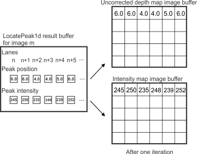
Note that instead of drawing results for each laser line after every grab, you can accumulate results in the result buffer, and then draw multiple rows in the destination image buffer by calling MimDraw() with Param2 set to M_ALL. In this case, you must set MimControl() with M_NUMBER_OF_FRAMES to the maximum number of frames (laser line images) for which results can be accumulated in the specified result buffer. When calling MimLocatePeak1d(), set M_FRAME_INDEX to the appropriate index in the result buffer which corresponds to the frame for which to store results.
The following animation illustrates the uncorrected depth map of an entire series of grabbed images.

The following image shows a single grabbed laser line image on the left, and the uncorrected depth map and intensity map that results from processing the entire series of grabbed images on the right:
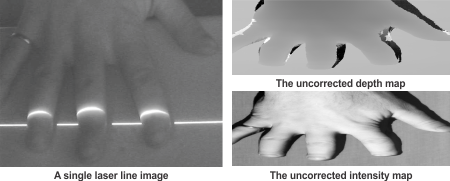
Note that the Y-size of the depth and intensity maps is determined by the number of laser line images in the sequence. In this example, the hand moved approximately 2 pixels per image capture so the Y-size of the depth and intensity maps is half of the source images.
Multiple peaks in a single lane
It is possible that there are multiple peaks in a lane which fit the specified requirements for a peak. This can occur when there is noise in the image, but frequently occurs due to reflections on the object or the background surface. To address this case, MimLocatePeak1d() can find and store peak information for several of the best peaks in each lane, using MimControl() with M_NUMBER_OF_PEAKS. After this control type is set, calling MimLocatePeak1d() establishes and stores the position and intensity for the specified number of peaks in each lane in the image. By analyzing the 1D locate peak result buffer, you can create a process that determines the most relevant peaks for the image.
To retrieve this peak information from the result buffer, call MimGetResultSingle(). You can specify to retrieve the peak information for one or all peaks in one or all lanes. The most common combination is to retrieve the peak information for each peak with a given index across all lanes. Typically, this is used to get an array of the best peaks (the first peak is the peak with the highest intensity in the lane, by default) in each lane.
You can specify how the multiple peaks are initially sorted in the result buffer using MimControl() with M_SORT_CRITERION. By default, the peaks are sorted by descending intensities, which means that the peak with the highest intensity, which is frequently the best peak, has an index of 0.
For instance, you can retrieve the positions of the highest intensity peaks in each lane of an image, using MimGetResultSingle() with M_PEAK_POSITION. With this information, you can create a process that identifies aberrant peaks. You could then retrieve the second best peak in the lanes that have aberrant peaks to create an array with only the correct peaks for the image.
Extraction of peaks from a multi-frame buffer
MimLocatePeak1d() supports the extraction of peaks from a multi-frame image buffer. A multi-frame image buffer is one that is composed of multiple adjacent frames, typically grabbed using frame burst technology. For information on multi-frame image buffers, see the Specifying the dimensions of a multi-frame image buffer subsection of the Specifying the dimensions of a data buffer section of Chapter 21: Data buffers.
To use a multi-frame image buffer with MimLocatePeak1d(), you must set the Y-size of each individual frame using MimControl() with M_FRAME_SIZE, and set MimControl() with M_NUMBER_OF_FRAMES to the maximum number of frames for which results can be accumulated in the result buffer. Note that the total number of frames (M_NUMBER_OF_FRAMES) can be different from the frame capacity of the source image buffer. For example, if the source image buffer has a 5-frame capacity and you have 10 total frames to process, 2 calls to MimLocatePeak1d() can be done before calling MimGetResultSingle(). Typically, you would set M_FRAME_INDEX to frame 0 on the first call to MimLocatePeak1d(); then, set it to frame 5 on the second call. Finally, it is important to set M_FRAME_INDEX such that the result buffer can hold all results produced from the call. That is, there must be enough indices available in the result buffer to accommodate results from all frames in the source image buffer.
The following code snippet shows how to extract peaks from a multi-frame image buffer.
/* Locate peak 1d context allocation. */
MIL_ID LocatePeakContextId = MimAlloc(MilSystemId, M_LOCATE_PEAK_1D_CONTEXT, M_DEFAULT, M_NULL);

/* Locate peak 1d result allocation. */
MIL_ID LocatePeakResultId = MimAllocResult(MilSystemId, M_DEFAULT, M_LOCATE_PEAK_1D_RESULT, M_NULL);

/**/
/* Set the maximum number of frames to store in the result. */
MimControl(LocatePeakContextId, M_NUMBER_OF_FRAMES, 100);

/* Set the Y-size of each frame in the image. */
MimControl(LocatePeakContextId, M_FRAME_SIZE, 32);

/* Set the minimum contrast for extraction. */
MimControl(LocatePeakContextId, M_MINIMUM_CONTRAST, 50);

/* Set the nominal peak width for extraction. */
MimControl(LocatePeakContextId, M_PEAK_WIDTH_NOMINAL, 10);

/* Set the peak width delta for extraction. */
MimControl(LocatePeakContextId, M_PEAK_WIDTH_DELTA, 10);

/* Set the maximum number of peaks per scan lane to extract per frame. */
MimControl(LocatePeakContextId, M_NUMBER_OF_PEAKS, 2);

/* Set the direction of the extraction process. */
MimControl(LocatePeakContextId, M_SCAN_LANE_DIRECTION, M_VERTICAL);

/**/
/* Set the sort parameters for the extracted peaks to strongest peak first. */
MimControl(LocatePeakResultId, M_SORT_CRITERION, M_PEAK_INTENSITY + M_SORT_DOWN);

/**/
/* Perform preprocessing. */
MimLocatePeak1d(LocatePeakContextId, SrcId, LocatePeakResultId, M_NULL, M_NULL, M_NULL, M_PREPROCESS, M_DEFAULT);

while (Processing)
   {
   /**/
   /* Perform peak extraction on multiple frames.*/
   MimLocatePeak1d(LocatePeakContextId, SrcId, LocatePeakResultId, M_DEFAULT, M_DEFAULT, M_DEFAULT, M_DEFAULT, M_DEFAULT);

   /* Extract the best peaks in all scan lanes of all frames. */
   MimGetResultSingle(LocatePeakResultId, M_SELECT_PEAK(M_ALL, 0), M_ALL, ResultType, UserPtr);

   /**/
   }
/**/
/* Release the locate peak 1d resources. */
MimFree(LocatePeakResultId);
MimFree(LocatePeakContextId);