Generating fully corrected depth and intensity maps
- See also

 Availability
 Previous
- Next

-
Optionally, rotate or transform the point cloud (using M3dimRotate() or M3dimMatrixTransform()) so that projecting the point cloud onto the XY-plane of its working coordinate system will result in the required depth map. See the Changing a depth map by rotating or transforming 3D points subsection of this section.
-
Optionally, call M3dimCalculateMapSize() to estimate a recommended depth map image buffer size from the source container's point cloud. Note that you can specify a 3D box geometry object to limit which points to include for the calculation. M3dimCalculateMapSize() makes a best estimate calculation for the depth map image buffer, based on the distance between points in X and Y in the source point cloud, such that most points map to their own pixel and with a minimum number of invalid points.
If you already know the depth map image buffer size with which you want to work, you can allocate it directly, without first calling M3dimCalculateMapSize().
-
Allocate an image buffer that will hold the depth map, using MbufAlloc2d(). If you are generating both a depth map and an intensity map, you must allocate a separate image buffer for each. The image buffer in which to store the intensity map must have the same dimensions (SizeX and SizeY) as the image buffer allocated for the depth map. Note that you can allocate a 3-band image buffer (using MbufAllocColor()) for the intensity map if the point cloud container's M_COMPONENT_REFLECTANCE or M_COMPONENT_INTENSITY component is also 3-band.
-
Call M3dimCalibrateDepthMap() to calibrate the allocated image buffer for the depth map. The calibration sets the real-world to pixel unit scale for the image buffer, and sets the real-world to gray level scale (M_GRAY_LEVEL_SIZE_Z) for depth values.
Note that you must perform steps 2 and 4 such that the bounding boxes for each operation are the same (typically, M3dimCalculateMapSize() and M3dimCalibrateDepthMap() use the same source point cloud or 3D geometry).
Note that once you have computed a calibration for the depth map image buffer (using M3dimCalibrateDepthMap()), you can use the results for multiple calls to M3dimProject(), without having to recalculate a calibration each time.
-
Call M3dimProject(), specifying the point cloud container that holds the point cloud and the image buffers that will hold the depth map and intensity map. After the projection, the resulting depth map will be fully corrected and include a valid Z-scale.
-
Allocate a 3-band LUT buffer using MbufAllocColor() with M_LUT. Ensure that your LUT buffer width is at least as large as the number of different possible intensities in the depth map (256 for 8-bit depth maps, 65536 for 16-bit depth maps).
-
Populate the LUT buffer with colors for each intensity using MgenLutFunction() with a colormap, such as M_COLORMAP_JET.
-
Optionally, to highlight invalid pixels, add the M_LAST_GRAY combination value. When specified, the color assigned to the highest index of the LUT is replaced. Set the b parameter to specify the replacement color. Specifying a value that is not among the colors in the LUT (for instance gray) allows you to find areas with invalid points more easily. Alternatively, you can use MbufPutColor2d() to replace elements (colors) in a LUT.
-
Associate the LUT buffer with the display using MdispLut(). This adds color to the image displayed on the screen, but does not affect the image itself. The grayscale depth map is not changed as a result of this function. You can associate a LUT buffer to a 3D display using M3dgraControl() with M_COLOR_USE_LUT set to M_TRUE. See the Applying LUTs subsection of the Color and display settings for 3D data section of Chapter 37: 3D Display and graphics for more information.
You can generate a fully corrected depth map from a point cloud or 3D geometry. To do so, use M3dimProject(), which projects the point cloud or 3D geometry onto the XY-plane (Z=0) of the working coordinate system, and converts 3D point information to depth map pixel values. You can also generate an intensity map from a point cloud.
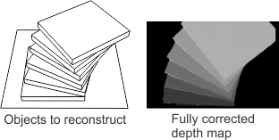
As an image, a depth map has pixels and a pixel coordinate system where the center of the top-left pixel is (0, 0). However, each pixel can be seen as a 3D coordinate, with the X- and Y-coordinates of a pixel in the depth map corresponding to X- and Y-coordinates of a 3D point (where pixel and world units are suitably scaled). The intensity of a pixel in a depth map corresponds to the Z-coordinate, or depth, of the point. For more information on the correspondence between pixel coordinates and world coordinates, see the Transforming coordinates from a depth map to a world coordinate system (or vice versa) subsection of the How coordinates and non-positional results are transformed section of Chapter 26: Calibrating your camera setup.
In addition to a depth map, you can also generate an intensity map from a point cloud. As with a depth map, the X- and Y-pixel coordinates of the intensity map correspond to the X- and Y-world coordinates of 3D points (where pixel and world units are suitably scaled). The difference between the two maps lies with what the intensities of their pixels correspond. In a depth map, the intensity of a given pixel corresponds to the height of the object at that point. In an intensity map, the intensity of a pixel corresponds to the luminous intensity of the object at that point. For more information on intensity maps, see the Generating the intensity map subsection of this section. Except when otherwise mentioned, everything in this section that refers to depth maps also includes intensity maps.
Steps to create a depth map
To create a depth map from a point cloud, you need to call M3dimProject() and specify the point cloud container and a calibrated image buffer to hold the depth map. M3dimProject() uses the calibration information of the image buffer so that projected points and depth information correspond to the X-size, Y-size, and Z-scale of the depth map image buffer. Note that M3dimProject() projects 3D points onto the XY-plane (Z=0) of the point cloud's working coordinate system, which are then mapped to depth map pixels.
The following steps provide a basic methodology for generating a fully corrected depth map from a point cloud:
Changing a depth map by rotating or transforming 3D points
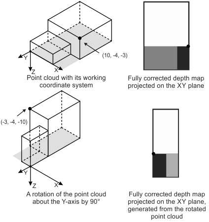
To generate a fully corrected depth map, M3dimProject() projects the points of the point cloud on the XY-plane (Z=0) of its working coordinate system. To obtain a different view of the point cloud in the resulting depth map, use M3dimRotate() or M3dimMatrixTransform() to rotate or transform (respectively) the 3D points before calling M3dimProject().
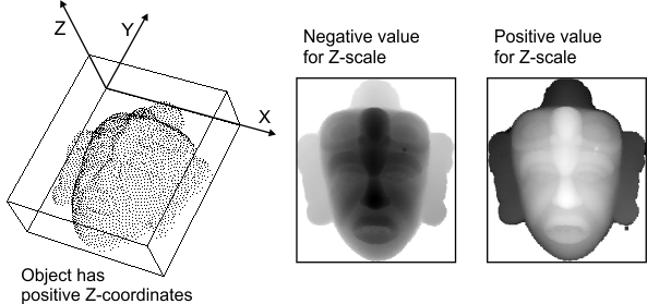
The following image illustrates generating 2 different depth maps from the same point cloud (the wire frame boxes are the objects from which the point clouds are created). Note that the ZSign parameter is set to M_NEGATIVE so that more negative Z-values are brighter in the depth map.
Defining the points to use
By default, if you pass a point cloud to M3dimCalculateMapSize() or M3dimCalibrateDepthMap(), the functions will use the bounding box of all points in the point cloud. If you want to exclude some points (for example, outliers), you can limit the calculation to points inside a box if you pass a 3D box geometry to M3dimCalculateMapSize(). You should pass the same box to M3dimCalibrateDepthMap(); doing so ensures that the calibrated image buffer passed to M3dimProject() will hold the required point data from inside the box. Optionally, you can apply a crop or mask to the point cloud using M3dimCrop() before calling M3dimProject() if you need to exclude further points.
If you want to calculate a bounding box that contains most of the points, but rejects outliers, you can use M3dimStat() with an M_STAT_CONTEXT_BOUNDING_BOX context that has M_BOUNDING_BOX_ALGORITHM set to M_ROBUST. See the Determining the bounding box of a point cloud subsection of the Calculating statistics on a point cloud or depth map section earlier in this chapter.
Estimating a recommended depth map image buffer size
Before calling M3dimProject() to generate a depth map, you can use M3dimCalculateMapSize() to estimate a recommended image buffer size in X and Y for the depth map. The recommended size is based on the given points and is optimized so that the resulting depth map is not too small or large. That is, you will not have a depth map where too many points have been projected into the same pixel (loss of information), or a depth map where the gaps between valid pixels are too large. M3dimCalculateMapSize(), by default, does all calculations for the depth map's dimensions. If required, you can set a fixed size along 1 dimension, and the function will calculate the necessary size of the other dimension (for either pixel size or image buffer size).
Note that using M3dimCalculateMapSize() to estimate a recommended depth map image buffer size is optional. Your 3D sensor might provide organized point clouds with standard XY-dimensions with which you want to work. In this case, you can specify the required dimensions directly when allocating the depth map image buffer, using MbufAlloc2d().
Establishing the world-to-pixel scale and the world-to-gray level scale of the depth map
You can let M3dimCalibrateDepthMap() automatically determine the world-to-pixel scale and world-to-gray level scale for the depth map.
How to calibrate the image buffer
Ultimately, you want a depth map with constant world-to-pixel and world-to-gray level scales. You can use M3dimCalibrateDepthMap() to determine the ratio between the specified point cloud's dimensions (measured in world units) and the depth map image buffer (measured in pixels), and automatically calibrate the image buffer with this information. Default settings use a square pixel size.
To inquire about a depth map's scale values, call McalInquire() with the identifier of the depth map image buffer and M_PIXEL_SIZE_X or M_PIXEL_SIZE_Y to inquire the real-world length in X or Y of one depth map pixel; inquire M_GRAY_LEVEL_SIZE_Z to obtain the step, in world units, along the Z-axis of the relative coordinate system represented by one gray level.
Specifying data placement in the destination image buffer
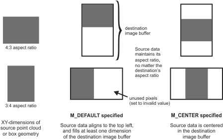
Depending on the source point cloud, it might not fit exactly within the destination image buffer's dimensions. When calling M3dimCalibrateDepthMap(), you can use the ControlFlag parameter to specify where to place valid values in the destination image buffer; you can set the parameter to M_DEFAULT or M_CENTER. In the M_DEFAULT case, the data aligns to the top left of the image buffer, and M3dimCalibrateDepthMap() calculates a pixel size such that the data extends at least the breadth of one dimension, and no data is lost along the other dimension. Leftover pixels are set to the invalid value, and are always located to the right or bottom of the valid data in the image buffer. In the M_CENTER case, valid data is centered in the image buffer and extends the full breadth of one dimension with no loss of data along the other dimension. Leftover pixels are located above and below or to the right and left of the valid data. Note that the source data maintains its aspect ratio, and is not affected by the destination's aspect ratio.
The following illustration shows source data placement in the destination image buffer.
Automatically setting the pixel aspect ratio
When using M3dimCalibrateDepthMap(), you can set the PixelSizeAspectRatio parameter to M_NULL so that projected data fits exactly onto the depth map image buffer, with no invalid rows or columns. This is useful, for example, when using a laser profiler to generate the source point cloud. Data along X depends on the camera resolution, while data along Y depends on the frame rate and the speed of the conveyor. The disparity between these dimensions makes it difficult to use a 1:1 pixel aspect ratio, and doing so would result in data loss in the X-direction, or gaps in the Y-dimension if a square pixel size was enforced. To ensure a calculated map size without gaps or data loss, and a corresponding exact fit of projected data into the depth map image buffer, use M3dimControl() with M_PIXEL_ASPECT_RATIO set to M_NULL when setting up the calculate map size 3D image processing context, and then use M3dimCalibrateDepthMap() with M_NULL when calibrating the destination image buffer.
Specifying the depth map intensity scale
MIL automatically sets the real-world to gray level scale M_GRAY_LEVEL_SIZE_Z when you call M3dimCalibrateDepthMap(). By default, M_GRAY_LEVEL_SIZE_Z is considered positive (M_POSITIVE), which means larger (more positive) Z-values have the brightest gray levels and smaller (more negative) Z-values are darker. To invert the gray level values, set the ZSign parameter to M_NEGATIVE.
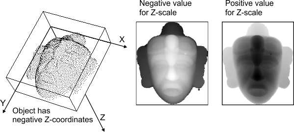
If the Z-axis points downward, the object is in the negative Z-region of the working coordinate system, and more negative Z-values indicate a higher surface and are darker in the depth map (assuming ZSign is set to M_POSITIVE). The following image shows the distribution of gray values when the object is in the positive or negative Z-region, and when ZSign is set to M_POSITIVE or M_NEGATIVE.
Saturating or ignoring points outside the depth map grayscale range
The depth map image buffer's grayscale range, along with M_GRAY_LEVEL_SIZE_Z, determines the maximum and minimum Z-values representable in the depth map. A point can be outside the depth map grayscale range. For instance, if the Z-axis scale is 0.02 cm/gray level in an 8-bit image, a point that is 1 cm high has a gray value of 50. At about 5 cm, the gray value reaches its maximum for the bit depth, 254.
Out-of-range points can occur if you pass M3dimCalibrateDepthMap() a point cloud or 3D box geometry that has different bounding box dimensions from the point cloud passed to M3dimProject().
If a point's Z-coordinate is not in the depth map grayscale range, the point is ignored or it saturates the pixel to which it maps. To specify which should occur, use M3dimProject() with the Options parameter set to M_DEFAULT to ignore or M_SATURATION to saturate.
By ignoring the point (M_DEFAULT), it is not included in the calculation of the depth map pixel's gray value. If there are other points that project onto this pixel, they are used to calculate the gray value. Otherwise, the pixel is rendered as invalid, and set to the buffer's maximum value (for example, 255 for an 8-bit buffer).
By saturating the point (M_SATURATION), the pixel's gray level value is clipped to either the maximum possible valid value (M_MAX - 1) or the minimum possible value (M_MIN), depending on whether the point maps to a value above or below the grayscale range.
Generating the intensity map
In an intensity map, the gray value of each pixel represents the luminosity of the original scene at this point. You can use this information to determine, for example, whether the surface is dark or light, or if the surface is reflective.
To generate the intensity map, allocate an image buffer and pass its identifier to M3dimProject(). The width and height of this buffer (the intensity map buffer) must be the same as the depth map image buffer. The number of bands of this buffer must match the number of bands of the source point cloud container's M_COMPONENT_REFLECTANCE or M_COMPONENT_INTENSITY component. Note that the image buffer for the intensity map does not have to be calibrated; M3dimProject() will calibrate it using the calibration information of the depth map image buffer. If you specify M_NULL as the identifier of the intensity map buffer, an intensity map is not generated.
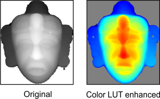
Adding color to a depth map for better visualization
To enhance your ability to differentiate small intensity differences in your depth map, you can apply a colormap LUT to the depth map image buffer, as in the image below.
The basic steps to apply a colormap to a depth map are as follows:
For more information on modifying how a 1-band image, such as a depth map, is displayed using a LUT buffer, see the Mapping 1-band images through a LUT upon display section of Chapter 23: Displaying an image.
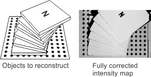
Gradually adding data to the depth map and intensity map image buffers
Normally, when you call M3dimProject(), it clears the depth map and intensity map buffers before writing to them. However, when the M_ACCUMULATE option is specified, M3dimProject() adds the data without clearing these buffers first. Before the first call to M3dimProject() and before starting to extract data of another object, do not use the M_ACCUMULATE option.
Point cloud projection example
For an illustration of projecting a point cloud to generate a depth map, see the following example.