
Filters
Filter values by
- Calibration context settings
- Image buffer settings
- 3d draw calibration context settings
| Click here to show toolbars of the Web Online Help System: show toolbars |
| MIL_ID ContextCalOrCalibratedMilObjectId, | //in |
| MIL_INT64 ControlType, | //in |
| MIL_DOUBLE ControlValue | //in |
This function allows you to control a specified setting of a camera calibration context, calibrated image, or 3D draw calibration context.
If you control a camera calibration setting of a calibrated image with an M_VECTOR_AND_RASTER ROI, the raster information will be discarded, causing the ROI to become an M_VECTOR ROI. See MbufSetRegion() for more information.
Specifies the identifier of the camera calibration context, calibrated image, or 3D draw calibration context.
Specifies the setting to change.
See the Parameter associations section for possible values that can be specified.
Specifies the setting's new value.
See the Parameter associations section for possible values that can be specified.
The tables below list possible values for the ControlType and ControlValue parameters.
The following ControlType and ControlValue parameter settings can be specified for a camera calibration context:
 For a camera calibration context For a camera calibration context
|
|||||||||||||||||||||||||||||||||||||||
|
|
Description | ||||||||||||||||||||||||||||||||||||||
| ControlValue | |||||||||||||||||||||||||||||||||||||||
|
Sets the plane in which the calibration points are defined. INQ |
|||||||||||||||||||||||||||||||||||||||
|
Same as M_ABSOLUTE_COORDINATE_SYSTEM. |
|||||||||||||||||||||||||||||||||||||||
|
Specifies that the calibration points are defined in the absolute coordinate system. |
|||||||||||||||||||||||||||||||||||||||
|
Specifies that the calibration points are defined in the relative coordinate system. |
|||||||||||||||||||||||||||||||||||||||
|
Sets whether the circles in a circle grid, used with McalGrid(), are lighter or darker than the background. INQ |
|||||||||||||||||||||||||||||||||||||||
|
Determines the appropriate setting automatically. |
|||||||||||||||||||||||||||||||||||||||
|
Specifies that the grid's circles are darker than the background. |
|||||||||||||||||||||||||||||||||||||||
|
Specifies that the grid's circles are lighter than the background. |
|||||||||||||||||||||||||||||||||||||||
|
Specifies that McalGrid() will look for a fiducial in the grid. INQ |
|||||||||||||||||||||||||||||||||||||||
|
Same as M_NONE. |
|||||||||||||||||||||||||||||||||||||||
|
Specifies that a Data Matrix code is used as a fiducial in a chessboard grid. |
|||||||||||||||||||||||||||||||||||||||
|
Specifies that there is no fiducial in the grid. |
|||||||||||||||||||||||||||||||||||||||
|
Specifies the hint angle used to establish the direction of the X-axis of the absolute (or relative) coordinate system, when calibrating with a partial chessboard grid. INQ |
|||||||||||||||||||||||||||||||||||||||
|
Specifies that no hint angle is used. |
|||||||||||||||||||||||||||||||||||||||
|
Specifies the hint angle, measured counter-clockwise. |
|||||||||||||||||||||||||||||||||||||||
|
Specifies the X-coordinate of the hint pixel. INQ |
|||||||||||||||||||||||||||||||||||||||
|
Same as M_NONE. |
|||||||||||||||||||||||||||||||||||||||
|
Specifies not to use a hint pixel. |
|||||||||||||||||||||||||||||||||||||||
|
Specifies the X-coordinate of the hint pixel, in the pixel coordinate system. |
|||||||||||||||||||||||||||||||||||||||
|
Specifies the Y-coordinate of the hint pixel. INQ |
|||||||||||||||||||||||||||||||||||||||
|
Same as M_NONE. |
|||||||||||||||||||||||||||||||||||||||
|
Specifies not to use a hint pixel. |
|||||||||||||||||||||||||||||||||||||||
|
Specifies the Y-coordinate of the hint pixel, in the pixel coordinate system. |
|||||||||||||||||||||||||||||||||||||||
|
Specifies whether McalGrid() can assume that the chessboard grid is complete. INQ |
|||||||||||||||||||||||||||||||||||||||
|
Specifies that McalGrid() will only calibrate the camera setup when a complete grid is found in the image. |
|||||||||||||||||||||||||||||||||||||||
|
Specifies that McalGrid() can calibrate the camera setup when a partial grid is found in the image. |
|||||||||||||||||||||||||||||||||||||||
|
Specifies how to handle potential outlying calibration points, using assumptions about the grid's shape in the image. INQ |
|||||||||||||||||||||||||||||||||||||||
|
Same as M_RECTANGLE. |
|||||||||||||||||||||||||||||||||||||||
|
Specifies to include all potential calibration points in the image; McalGrid() will not look for the boundary of the real-world grid. In this case, the shape of the partial grid is not bound. Set this value when the partial grid in the image is not a rectangle. This can be either when the real-world grid is a rectangle, but is occluded by an object in the image, as in the image on the left, or when the real-world grid is not a rectangle, as in the image on the right. 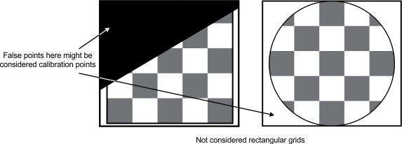
With no fixed shape, no potential calibration point can be excluded as an outlier because it is not clear where the boundary of the partial grid is. This could lead to outlying false calibration points being included in the camera calibration, which would reduce the calibration's precision. In this case, it is highly recommended to check all calibration points extracted from the image using McalGrid() are valid, using McalDraw() with M_DRAW_IMAGE_POINTS. Specifies to include all potential calibration points in the image; McalGrid() will not look for the boundary of the real-world grid. |
|||||||||||||||||||||||||||||||||||||||
|
Specifies to exclude potential calibration points in the image that McalGrid() determines are outside the boundaries of the partial grid. In this case, the shape of the partial grid is a rectangle. Set this value if the real-world grid is rectangular and the image of the partial grid is not occluded by any objects in the image. Note that a partial grid is still considered rectangular if the boundary of the partial grid is obscured by the end of the image. 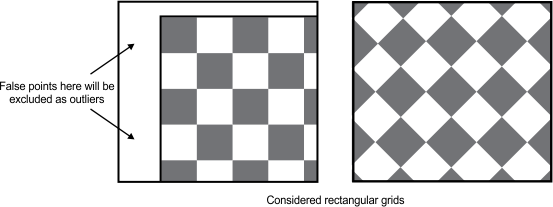
In this case, McalGrid() will look for the boundaries of the partial grid in the image. This allows the possibility of excluding false calibration points outside of the grid. Specifies to exclude potential calibration points in the image that McalGrid() determines are outside the boundaries of the partial grid. |
|||||||||||||||||||||||||||||||||||||||
|
Creates a rigid link between the camera coordinate system and the tool coordinate system. INQ |
|||||||||||||||||||||||||||||||||||||||
|
Same as M_ENABLE. |
|||||||||||||||||||||||||||||||||||||||
|
Specifies to remove the link between the two coordinate systems, allowing both to be moved independently. |
|||||||||||||||||||||||||||||||||||||||
|
Specifies to link the two coordinate systems, allowing both to be moved together. |
|||||||||||||||||||||||||||||||||||||||
|
Specifies the maximum number of iterations to attempt to fit the provided points when calculating the new position of the camera or relative coordinate system, when using McalList() and McalGrid() with M_DISPLACE_CAMERA_COORD or M_DISPLACE_RELATIVE_COORD respectively. INQ |
|||||||||||||||||||||||||||||||||||||||
|
Specifies the default value; the default value is 250. |
|||||||||||||||||||||||||||||||||||||||
|
Specifies the number of expected outliers. |
|||||||||||||||||||||||||||||||||||||||
|
Specifies the maximum number of possible outliers that can occur in the dataset used by McalList() or McalGrid() with M_DISPLACE_CAMERA_COORD or M_DISPLACE_RELATIVE_COORD. INQ |
|||||||||||||||||||||||||||||||||||||||
|
Specifies the default value; the default value is 0. |
|||||||||||||||||||||||||||||||||||||||
|
Specifies the number of expected outliers. |
|||||||||||||||||||||||||||||||||||||||
|
Sets the X-position of the tool coordinate system in the absolute coordinate system. INQ |
|||||||||||||||||||||||||||||||||||||||
|
Specifies the X-coordinate, in world units. |
|||||||||||||||||||||||||||||||||||||||
|
Sets the Y-position of the tool coordinate system in the absolute coordinate system. INQ |
|||||||||||||||||||||||||||||||||||||||
|
Specifies the Y-coordinate, in world units. |
|||||||||||||||||||||||||||||||||||||||
|
Sets the Z-position of the tool coordinate system in the absolute coordinate system. INQ |
|||||||||||||||||||||||||||||||||||||||
|
Specifies the default value; the default value is 0.0. |
|||||||||||||||||||||||||||||||||||||||
|
Specifies the Z-coordinate, in world units. |
|||||||||||||||||||||||||||||||||||||||
|
Sets whether to use a cache to accelerate the McalTransformImage() function. INQ |
|||||||||||||||||||||||||||||||||||||||
|
Specifies not to use a cache. |
|||||||||||||||||||||||||||||||||||||||
|
Specifies to use a cache. |
|||||||||||||||||||||||||||||||||||||||
The following ControlType and ControlValue parameter settings can be specified only for a 3D-based camera calibration context ( M_TSAI_BASED or M_3D_ROBOTICS):
|
For a 3D-based camera calibration
context
|
|||||||||||||||||||||||||||||||||||||||
|
|
Description | ||||||||||||||||||||||||||||||||||||||
| ControlValue | |||||||||||||||||||||||||||||||||||||||
|
Sets the width-to-height ratio of the individual elements of the CCD. INQ |
|||||||||||||||||||||||||||||||||||||||
|
Specifies that the width and height of the CCD element are equal. |
|||||||||||||||||||||||||||||||||||||||
|
Specifies the value of the width of a CCD element divided by its height. |
|||||||||||||||||||||||||||||||||||||||
|
Sets the X-coordinate of the intersection of the camera's optical axis and the image plane. INQ |
|||||||||||||||||||||||||||||||||||||||
|
Specifies half of the image's width, in pixels. |
|||||||||||||||||||||||||||||||||||||||
|
Specifies the X-coordinate, in pixels. |
|||||||||||||||||||||||||||||||||||||||
|
Sets the Y-coordinate of the intersection of the camera's optical axis and the image plane. INQ |
|||||||||||||||||||||||||||||||||||||||
|
Specifies half of the image's height, in pixels. |
|||||||||||||||||||||||||||||||||||||||
|
Specifies the Y-coordinate, in pixels. |
|||||||||||||||||||||||||||||||||||||||
The following ControlType and ControlValue parameter settings can be specified for a calibrated image:
|
For a calibrated image
|
|||||||||||||||||||||||||||||||||||||||
|
|
Description | ||||||||||||||||||||||||||||||||||||||
| ControlValue | |||||||||||||||||||||||||||||||||||||||
|
Sets the X-offset of a child buffer, relative to its highest order calibrated parent buffer. INQ |
|||||||||||||||||||||||||||||||||||||||
|
Specifies the X-offset, relative to the child buffer's highest order calibrated parent buffer. |
|||||||||||||||||||||||||||||||||||||||
|
Sets the Y-offset of a child buffer, relative to its highest order calibrated parent buffer. INQ |
|||||||||||||||||||||||||||||||||||||||
|
Specifies the Y-offset, relative to the child buffer's highest order calibrated parent buffer. |
|||||||||||||||||||||||||||||||||||||||
The following ControlType and ControlValue parameter settings can be specified for a calibrated image:
|
For a calibrated and corrected image
|
|||||||||||||||||||||||||||||||||||||||
|
|
Description | ||||||||||||||||||||||||||||||||||||||
| ControlValue | |||||||||||||||||||||||||||||||||||||||
|
Sets the difference in height corresponding to a difference of one gray level in a fully-corrected depth map. INQ |
|||||||||||||||||||||||||||||||||||||||
|
Specifies that the image is not a depth map. |
|||||||||||||||||||||||||||||||||||||||
|
Specifies the height, in world units, corresponding to a difference of one gray level. |
|||||||||||||||||||||||||||||||||||||||
|
Sets the real-world Z-offset of a gray level of 0 in the corrected image, useful in depth maps. INQ |
|||||||||||||||||||||||||||||||||||||||
|
Specifies the base height of a gray level of 0. |
|||||||||||||||||||||||||||||||||||||||
The following ControlType and ControlValue parameter settings can be specified for a 3D draw calibration context:
|
For a 3D draw calibration context
|
|||||||||||||||||||||||||||||||||||||||
|
|
Description | ||||||||||||||||||||||||||||||||||||||
| ControlValue | |||||||||||||||||||||||||||||||||||||||
|
Sets whether to draw the absolute coordinate system's axes. INQ |
|||||||||||||||||||||||||||||||||||||||
|
Same as M_ENABLE. |
|||||||||||||||||||||||||||||||||||||||
|
Specifies not to draw the absolute coordinate system's axes. |
|||||||||||||||||||||||||||||||||||||||
|
Specifies to draw the absolute coordinate system's axes. |
|||||||||||||||||||||||||||||||||||||||
|
Sets whether to draw the camera coordinate system's axes. INQ |
|||||||||||||||||||||||||||||||||||||||
|
Same as M_ENABLE. |
|||||||||||||||||||||||||||||||||||||||
|
Specifies not to draw the camera coordinate system's axes. |
|||||||||||||||||||||||||||||||||||||||
|
Specifies to draw the camera coordinate system's axes. |
|||||||||||||||||||||||||||||||||||||||
|
Sets the name to draw for the camera coordinate system; the initial value is "Camera". INQ |
|||||||||||||||||||||||||||||||||||||||
|
Casts the address of the string identifying the camera coordinate system's name, from a MIL_CONST_TEXT_PTR to a MIL_INT. |
|||||||||||||||||||||||||||||||||||||||
| Parameters | |||||||||||||||||||||||||||||||||||||||
|
This parameter specifies the string whose address to cast. |
|||||||||||||||||||||||||||||||||||||||
|
|||||||||||||||||||||||||||||||||||||||
|
Sets the length at which to draw the specified coordinate system's axes. INQ |
|||||||||||||||||||||||||||||||||||||||
|
Specifies the default value; the default value is 50.0. |
|||||||||||||||||||||||||||||||||||||||
|
Specifies the length (in world units) at which to draw the axes of the specified coordinate system. |
|||||||||||||||||||||||||||||||||||||||
|
Sets whether to draw the frustum of the camera's view. INQ |
|||||||||||||||||||||||||||||||||||||||
|
Same as M_ENABLE. |
|||||||||||||||||||||||||||||||||||||||
|
Specifies not to draw the frustum. |
|||||||||||||||||||||||||||||||||||||||
|
Specifies to draw the frustum. |
|||||||||||||||||||||||||||||||||||||||
|
Sets the frustum's color. INQ |
|||||||||||||||||||||||||||||||||||||||
|
Same as M_COLOR_YELLOW. |
|||||||||||||||||||||||||||||||||||||||
|
Specifies an RGB value to draw in an 8-bit, 3-band buffer. |
|||||||||||||||||||||||||||||||||||||||
| Parameters | |||||||||||||||||||||||||||||||||||||||
|
Specifies the red component, as a value between 0 and 255. |
|||||||||||||||||||||||||||||||||||||||
|
Specifies the green component, as a value between 0 and 255. |
|||||||||||||||||||||||||||||||||||||||
|
Specifies the blue component, as a value between 0 and 255. |
|||||||||||||||||||||||||||||||||||||||
|
Specifies the color black. |
|||||||||||||||||||||||||||||||||||||||
|
Specifies the color blue. |
|||||||||||||||||||||||||||||||||||||||
|
Specifies the color bright gray. |
|||||||||||||||||||||||||||||||||||||||
|
Specifies the color cyan. |
|||||||||||||||||||||||||||||||||||||||
|
Specifies the color dark blue. |
|||||||||||||||||||||||||||||||||||||||
|
Specifies the color dark cyan. |
|||||||||||||||||||||||||||||||||||||||
|
Specifies the color dark green. |
|||||||||||||||||||||||||||||||||||||||
|
Specifies the color dark magenta. |
|||||||||||||||||||||||||||||||||||||||
|
Specifies the color dark red. |
|||||||||||||||||||||||||||||||||||||||
|
Specifies the color dark yellow. |
|||||||||||||||||||||||||||||||||||||||
|
Specifies the color gray. |
|||||||||||||||||||||||||||||||||||||||
|
Specifies the color green. |
|||||||||||||||||||||||||||||||||||||||
|
Specifies the color light blue. |
|||||||||||||||||||||||||||||||||||||||
|
Specifies the color light gray. |
|||||||||||||||||||||||||||||||||||||||
|
Specifies the color light green. |
|||||||||||||||||||||||||||||||||||||||
|
Specifies the color light white. |
|||||||||||||||||||||||||||||||||||||||
|
Specifies the color magenta. |
|||||||||||||||||||||||||||||||||||||||
|
Specifies the color red. |
|||||||||||||||||||||||||||||||||||||||
|
Specifies the color white. |
|||||||||||||||||||||||||||||||||||||||
|
Specifies the color yellow. |
|||||||||||||||||||||||||||||||||||||||
|
Specifies no color. |
|||||||||||||||||||||||||||||||||||||||
|
Sets whether to draw the relative coordinate system's axes. INQ |
|||||||||||||||||||||||||||||||||||||||
|
Same as M_ENABLE. |
|||||||||||||||||||||||||||||||||||||||
|
Specifies not to draw the relative coordinate system's axes. |
|||||||||||||||||||||||||||||||||||||||
|
Specifies to draw the relative coordinate system's axes. |
|||||||||||||||||||||||||||||||||||||||
|
Sets the name to draw for the relative coordinate system; the initial value is "Relative". INQ |
|||||||||||||||||||||||||||||||||||||||
|
Casts the address of the string identifying the relative coordinate system's name, from a MIL_CONST_TEXT_PTR to a MIL_INT. |
|||||||||||||||||||||||||||||||||||||||
| Parameters | |||||||||||||||||||||||||||||||||||||||
|
This parameter specifies the string whose address to cast. |
|||||||||||||||||||||||||||||||||||||||
|
|||||||||||||||||||||||||||||||||||||||
|
Sets whether to draw the relative XY plane. INQ |
|||||||||||||||||||||||||||||||||||||||
|
Same as M_ENABLE. |
|||||||||||||||||||||||||||||||||||||||
|
Specifies not to draw the relative XY plane. |
|||||||||||||||||||||||||||||||||||||||
|
Specifies to draw the relative XY plane. |
|||||||||||||||||||||||||||||||||||||||
|
Sets the relative XY plane's fill color. INQ |
|||||||||||||||||||||||||||||||||||||||
|
Same as M_AUTO_COLOR. |
|||||||||||||||||||||||||||||||||||||||
|
Specifies an RGB value to draw in an 8-bit, 3-band buffer. |
|||||||||||||||||||||||||||||||||||||||
| Parameters | |||||||||||||||||||||||||||||||||||||||
|
Specifies the red component, as a value between 0 and 255. |
|||||||||||||||||||||||||||||||||||||||
|
Specifies the green component, as a value between 0 and 255. |
|||||||||||||||||||||||||||||||||||||||
|
Specifies the blue component, as a value between 0 and 255. |
|||||||||||||||||||||||||||||||||||||||
|
Specifies either the color white or the texture image. |
|||||||||||||||||||||||||||||||||||||||
|
Specifies the color black. |
|||||||||||||||||||||||||||||||||||||||
|
Specifies the color blue. |
|||||||||||||||||||||||||||||||||||||||
|
Specifies the color bright gray. |
|||||||||||||||||||||||||||||||||||||||
|
Specifies the color cyan. |
|||||||||||||||||||||||||||||||||||||||
|
Specifies the color dark blue. |
|||||||||||||||||||||||||||||||||||||||
|
Specifies the color dark cyan. |
|||||||||||||||||||||||||||||||||||||||
|
Specifies the color dark green. |
|||||||||||||||||||||||||||||||||||||||
|
Specifies the color dark magenta. |
|||||||||||||||||||||||||||||||||||||||
|
Specifies the color dark red. |
|||||||||||||||||||||||||||||||||||||||
|
Specifies the color dark yellow. |
|||||||||||||||||||||||||||||||||||||||
|
Specifies the color gray. |
|||||||||||||||||||||||||||||||||||||||
|
Specifies the color green. |
|||||||||||||||||||||||||||||||||||||||
|
Specifies the color light blue. |
|||||||||||||||||||||||||||||||||||||||
|
Specifies the color light gray. |
|||||||||||||||||||||||||||||||||||||||
|
Specifies the color light green. |
|||||||||||||||||||||||||||||||||||||||
|
Specifies the color light white. |
|||||||||||||||||||||||||||||||||||||||
|
Specifies the color magenta. |
|||||||||||||||||||||||||||||||||||||||
|
Specifies the color red. |
|||||||||||||||||||||||||||||||||||||||
|
Specifies the color white. |
|||||||||||||||||||||||||||||||||||||||
|
Specifies the color yellow. |
|||||||||||||||||||||||||||||||||||||||
|
Specifies no color. |
|||||||||||||||||||||||||||||||||||||||
|
Specifies to use the image passed to McalDraw3d() with RelXYPlaneTextureImageBufId, when drawing the relative XY plane. |
|||||||||||||||||||||||||||||||||||||||
|
Sets the relative XY plane's outline color. INQ |
|||||||||||||||||||||||||||||||||||||||
|
Same as M_COLOR_WHITE. |
|||||||||||||||||||||||||||||||||||||||
|
Specifies an RGB value to draw in an 8-bit, 3-band buffer. |
|||||||||||||||||||||||||||||||||||||||
| Parameters | |||||||||||||||||||||||||||||||||||||||
|
Specifies the red component, as a value between 0 and 255. |
|||||||||||||||||||||||||||||||||||||||
|
Specifies the green component, as a value between 0 and 255. |
|||||||||||||||||||||||||||||||||||||||
|
Specifies the blue component, as a value between 0 and 255. |
|||||||||||||||||||||||||||||||||||||||
|
Specifies the color black. |
|||||||||||||||||||||||||||||||||||||||
|
Specifies the color blue. |
|||||||||||||||||||||||||||||||||||||||
|
Specifies the color bright gray. |
|||||||||||||||||||||||||||||||||||||||
|
Specifies the color cyan. |
|||||||||||||||||||||||||||||||||||||||
|
Specifies the color dark blue. |
|||||||||||||||||||||||||||||||||||||||
|
Specifies the color dark cyan. |
|||||||||||||||||||||||||||||||||||||||
|
Specifies the color dark green. |
|||||||||||||||||||||||||||||||||||||||
|
Specifies the color dark magenta. |
|||||||||||||||||||||||||||||||||||||||
|
Specifies the color dark red. |
|||||||||||||||||||||||||||||||||||||||
|
Specifies the color dark yellow. |
|||||||||||||||||||||||||||||||||||||||
|
Specifies the color gray. |
|||||||||||||||||||||||||||||||||||||||
|
Specifies the color green. |
|||||||||||||||||||||||||||||||||||||||
|
Specifies the color light blue. |
|||||||||||||||||||||||||||||||||||||||
|
Specifies the color light gray. |
|||||||||||||||||||||||||||||||||||||||
|
Specifies the color light green. |
|||||||||||||||||||||||||||||||||||||||
|
Specifies the color light white. |
|||||||||||||||||||||||||||||||||||||||
|
Specifies the color magenta. |
|||||||||||||||||||||||||||||||||||||||
|
Specifies the color red. |
|||||||||||||||||||||||||||||||||||||||
|
Specifies the color white. |
|||||||||||||||||||||||||||||||||||||||
|
Specifies the color yellow. |
|||||||||||||||||||||||||||||||||||||||
|
Specifies no color. |
|||||||||||||||||||||||||||||||||||||||
|
Sets the relative XY plane's opacity. INQ |
|||||||||||||||||||||||||||||||||||||||
|
Specifies the default value; the default value is 20.0. |
|||||||||||||||||||||||||||||||||||||||
|
Specifies the relative XY plane's opacity. |
|||||||||||||||||||||||||||||||||||||||
|
Sets whether to draw the robot base coordinate system's axes. INQ |
|||||||||||||||||||||||||||||||||||||||
|
Same as M_ENABLE. |
|||||||||||||||||||||||||||||||||||||||
|
Specifies not to draw the robot base coordinate system's axes. |
|||||||||||||||||||||||||||||||||||||||
|
Specifies to draw the robot base coordinate system's axes. |
|||||||||||||||||||||||||||||||||||||||
|
Sets whether to draw the tool coordinate system's axes. INQ |
|||||||||||||||||||||||||||||||||||||||
|
Same as M_DISABLE. |
|||||||||||||||||||||||||||||||||||||||
|
Specifies not to draw the tool coordinate system's axes. |
|||||||||||||||||||||||||||||||||||||||
|
Specifies to draw the tool coordinate system's axes. |
|||||||||||||||||||||||||||||||||||||||
1 If you are passing the value in a variable, don't enclose it in MIL_TEXT().
|
void McalControlInt64
(MIL_ID
ContextCalOrCalibratedMilObjectId, MIL_INT64 ControlType,
MIL_INT64 ControlValue)
Parameters
ContextCalOrCalibratedMilObjectId See ContextCalOrCalibratedMilObjectId of the main function for a description. ControlType See ControlType of the main function for a description. ControlValue See ControlValue of the main function for a description. |
|
void McalControlDouble
(MIL_ID
ContextCalOrCalibratedMilObjectId, MIL_INT64 ControlType,
MIL_DOUBLE ControlValue)
Parameters
ContextCalOrCalibratedMilObjectId See ContextCalOrCalibratedMilObjectId of the main function for a description. ControlType See ControlType of the main function for a description. ControlValue See ControlValue of the main function for a description. |
| Header | Include mil.h. |
| Library | Use mil.lib; milcal.lib. |
| DLL | Requires mil.dll; milcal.dll. |
 Availability